Not that I’m aware of.
Cool, thanks for doing the test. I may be able to live with 2.4khz and the reduced pwm range.
Got my OSHpark boards today but while laying out the parts to build one I realized that I’m still waiting on the QX7136s. ![]()
Maybe I’m not thinking correctly, but in my mind while the pwm range is reduced, but the light output range is not. We still have sub-lumen lows and full on, we just have less notches in between. I feel like 191 notches is still plenty to find what mode levels you want.
………
I’m using 2.4khz myself. Coincedentally, there are also fewer modifications needed to have STAR work on this driver than using the previous way.
I think you’re right, beyond limiting ramping smoothness and just being a bit less intuitive to set up the modes I think that will work fine.
There might be some efficiency losses perhaps?
If you’re not fed up with firmware tinkering, you could change the low fuse to 0x6a and flash it again with the same firmware.
I believe that should up the CPU speed and change the pwm frequency to 4.7khz.
If I understand the chart posted by HarleyQuinn correctly, the CPU frequency is primarily changed by the low fuse bit: i.e (0x*5) for 4.8Mhz and (0x*a) for 9.6Mhz.
Not sure if the firmware will play nice without also changing “#define F_CPU” to match the new frequency though.
Really wish I could be playing with this stuff myself. Also keen to scope the fet output and see how it looks/responds at the different PWM frequences.
Cheers
I normally would love to tinker some more, but unfortunately I packed it into a light already and would prefer to not take it out (it was a tight fit). I hope to post pictures of my build tonight.
No worries ![]()
Hopefully my 7136s won’t take too long to get here and I’ll run through a bunch of test then.
Cheers
Linus
In some other threads I read that upping the cpu frequency will increase power usage and heat (duh). I wouldn’t be too worried normally, but in an e-switch build I’m worried it would bump the parasitic drain up to unacceptable levels.
Yeah sure it’s probably not a good idea in a single cell setup or with a momentary as you mention. Was just curious what the limit of the 7136/fet is in terms of max PWM freq.
I think 4.7khz PWM shouldn’t really be visible anymore so that would be nice.
I’ll be interested to see what you find.
Was delighted to see the 7136s chips finally get here today, so I built up a test board and did a bit of testing.
Build report:
A self inflicted nightmare of epic proportions. I won’t get into too many details but it was pure frustration, nothing at all to do with the design of the board really. Just…I really miss having a hot air gun. ![]()
-
Then I forgot that this board actually has a trace for Turbo bypass and needs a firmware tweak to actually turn on regulation. Running stock STAR Offtime the thing is constantly in some kind of direct drive! So be warned!
Of course that didn’t click with me until after I had melted a couple sense resistors and blown one of my long suffering test XMLs to smithereens :_(
I remember Wight saying something about putting the Bypass pin into High impedance mode or something, but at that stage I couldn’t be bothered to figure out how to change it in firmware so I just cut the Trace and continued along my merry way. ![]()
Regulation was then working fine until the light was on high for more than a few seconds…then it just turned off. Some components get quite hot so I figured something went poof, but no all was fine. MCU pwm looked normal, sense resistor still there…all looked fine except the 7136 was no longer outputting anything. Damn must have killed it, maybe my crappy frustrated soldering?
I ended up replacing the 7136 3 times thinking I’d heat damaged it and it was dying prematurely on me. A few seconds on high and all would go dark.
Turned out it was a patch of unmelted solder paste underneath the mosfet that would partially short out the gate pin once the thing got up to temp…urgh!
This is why I like my mosfets nice and big! Haha ![]()
-
Alrighty, so after all that mess here goes the first batch of testing.
I wanted to get to the bottom of why frequency has such a drastic affect on the pwm performance of the driver so I hooked up my Rigol and went to town.
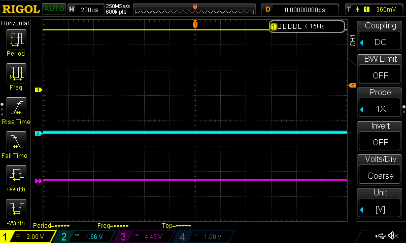
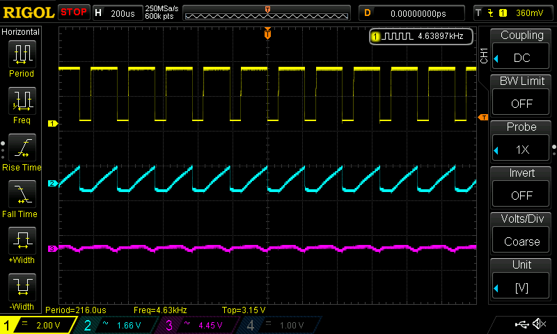
I probed the MCU pwm output (Channel 1), the 7136 output/gate signal (Channel 2) and the drain output of the mosfet (Channel 3).
Note: Ch2 and 3 are AC coupled so they jump around a bit, should have locked them down with DC but hey, I’m new at this scoping business ![]()
In any case it’s the shape of the curves that matter not the absolute measurements here I think.
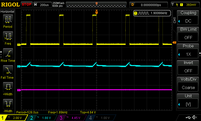
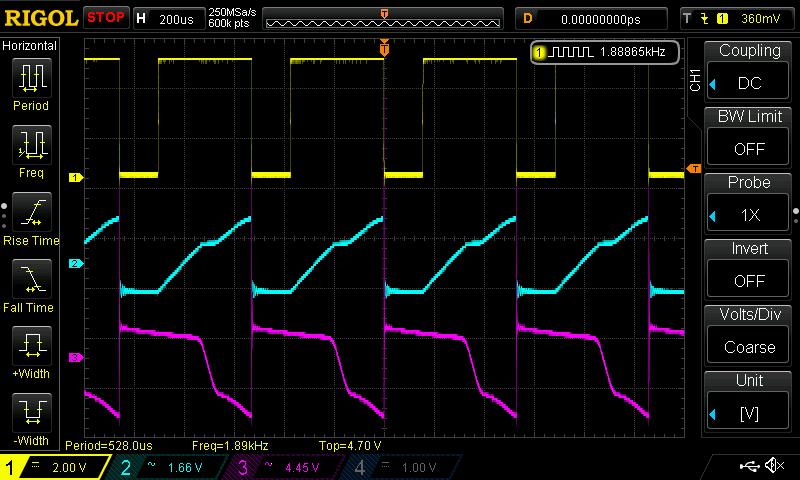
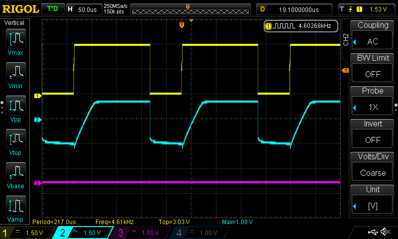
Here is what things look like at 1khz: i.e Phase correct / 4.8Mhz / 8x divider
PWM: 30 - No light, with warm leds very very dim moon mode
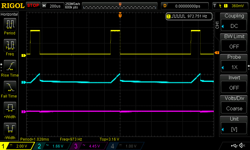
PWM: 60 - Low output
PWM: 100
PWM: 180
PWM: 255 (Just for good measure)
So as expected things work ok at 1khz. And it’s also clear to me what the issue is here.
The 7136 shows a very clear ramp up behaviour on it’s output, it’s pretty slow and even at 1khz it only manages to fully turn on it’s output during a cycle when it’s set to 100 pwm or higher. Anything below that it’s going to start ramping up but then get’s cut off. That has a knock on effect on the mosfet, which also takes some time to get up to speed. At 30pwm you can see the 7136 start ramping up a fair way but it’s not enough to make any real impact on the mosfet so the leds stay dark.
Usable Range: 30-255
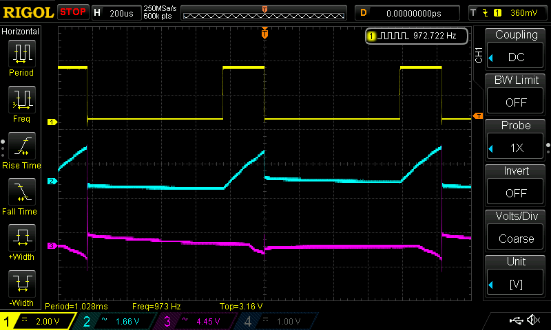
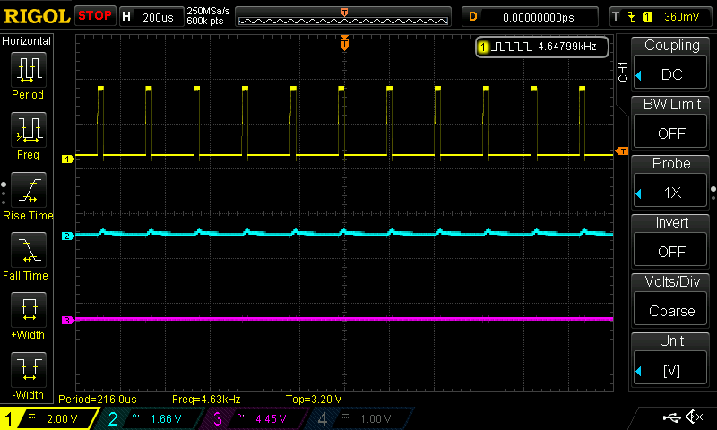
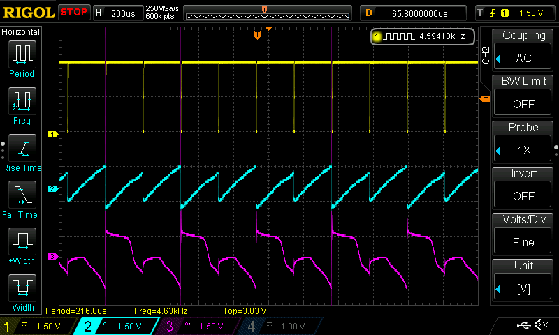
2.4 khz i.e Fast PWM / 4.8Mhz / 8x divider
PWM: 30 - No light
PWM: 60 - Barely on Moon mode, very very dim
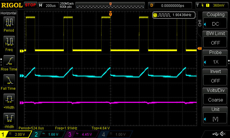
PWM: 100
PWM: 180
PWM: 255 (Just for good measure)
It’s clear to see the PWM range compression taking place as the frequency ramps up, a moon mode at ~60pwm also matches up well with what pilotdog68 reported seeing. This is at 2.4khz and I think still a good usable range, unfortunately PWM flicker is still apparent at this frequency. Better than 1khz for sure and you have to look for it but it’s definitely still there. Sweeping your eyes back and forth quickly reveals the evil flicker ![]()
Usable Range: 60-255
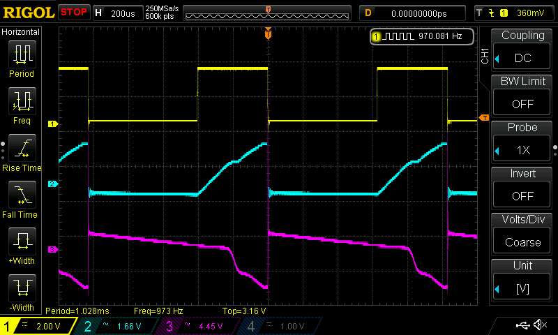
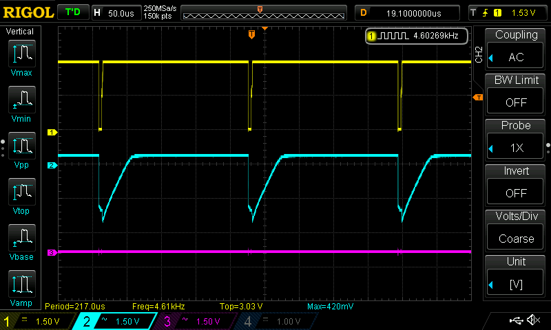
Hoping for a still usable range with less visible flicker I reran the test at 4.7khz i.e : Fast PWM / 9.6Mhz / 8x divider
———————————————————————————————————————————————————————-
PWM: 30 - No light
PWM: 60 - No light
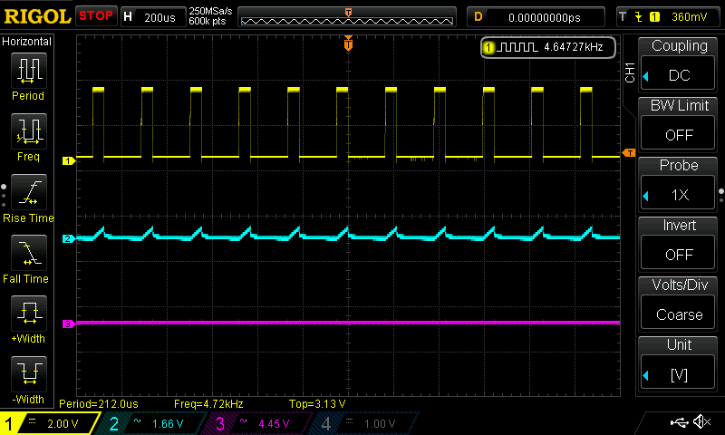
PWM: 100 - No light
PWM: 180 - Yay a few stray photons - A dim but usable moon mode
Ahem, well that’s not great is it. Moon mode at 180pwm! ![]()
That said I need to test a bit more and see if this is enough of a PWM range to get some usable spacing on the modes. I suspect it may be workable with some specific mode picking. Also by looking at that one moon mode, I can’t detect any flicker at this speed. Maybe it will still be obvious with higher output but I’m optimistic.
“Usable?” range 180-155
Edit: Nope not a usable range at all. It’s all moon modes until you hit 255. Even 253 is very dim, like dim enough to look directly at the led… dim ![]()
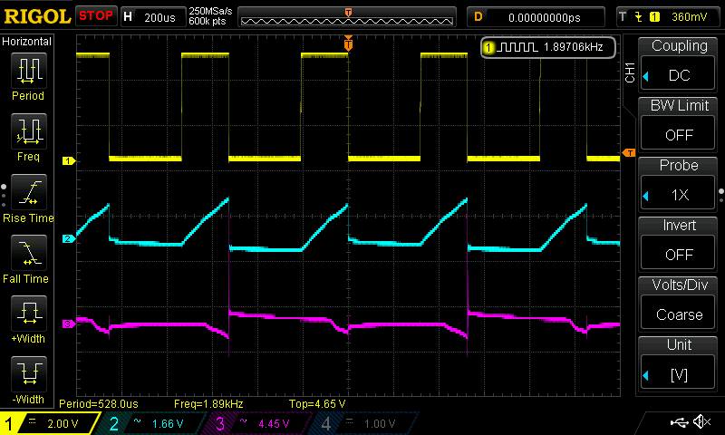
Also some really funky stuff happens to the mosfet waveform at this stage.
Yuck!
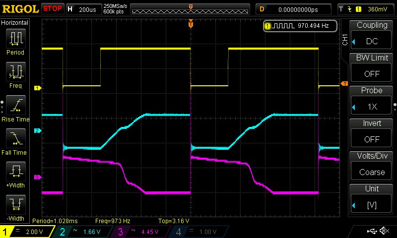
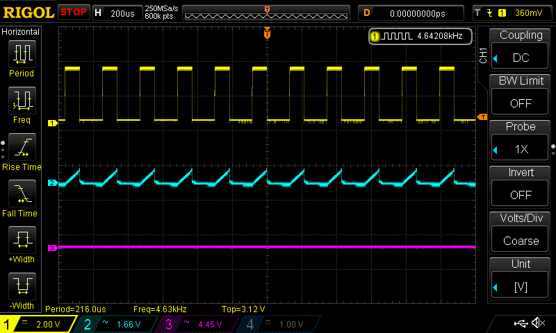
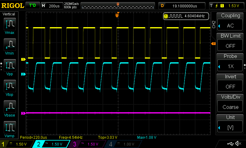
Finally I wanted to know exactly what the components do on a 0-100% turn on and how long everything takes to settle into place. Fairly tricky to capture actually, since I was using a clicky and if simply left to bang on it leaves some godawful noise on the waveforms. Gently does it! ![]()
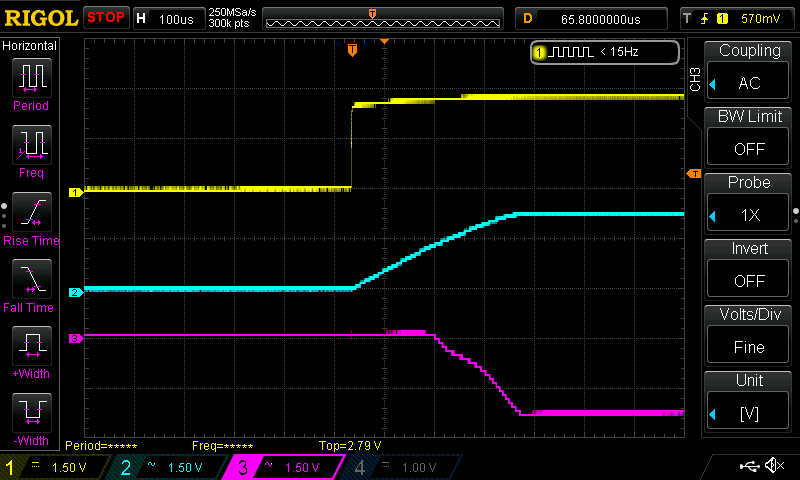
Looks to me like the 7136 takes almost exactly 300uS to ramp up to fully on and the mosfet has a delay of another 150uS after the start of the ramp before it does anything.
I’m still not sure how threshold voltage, gate charge, gate resistance or timing characteristics play into this behaviour but this looks like a very good method for finding out! ![]()
Anyone want to send me a spare DNT30N02 to compare? :bigsmile:
In the meantime I think I’ll just slap a couple of random mosfets on there and see how they respond, then cross check to see what specs may be contributing to those differences.
Fun times ![]()
Great post LinusHofmann!
I was unable to get multiple channels doing what I wanted like you did when I scoped the thing. I’ll have to take another crack at it. I may end up having to ask for some specific advice when I do.
In the text I quoted above you pick out the 7136 as the culprit for the slow rise on the DRV / gate trace. Remember that there are two ends to that trace, DRV on the 7136 and gate on the MOSFET. Both of those devices have an effect on that behavior.
Of course you’re right, nothing is operating on it’s own and I’m far from the right person to make the call on what’s actually going on here. I just saw that very consistent and mostly linear ramp up behaviour on the 7136 trace and thought it looked like a deliberately controlled thing. Maybe to help ease into regulation or something like that? Could be way off target of course.
Is there a way to scope the 7136 output without a mosfet gate attached to it?
Sure, just disconnect the gate. If you remove the MOSFET entirely the 7136 will attempt to fully open the gate as quickly as possible. This should not harm anything.
Cool will try that, didn’t think it would function properly without something attached.
‘properly’ is relative. With the sense voltage at a steady 0v we will not get ‘normal’ operation. All this test will really show is whether the slow rise is a 100% arbitrary characteristic or not. It’s worth checking IMO.
Well without the fet, output from the 7136 shoots up to 7.62v instantly then falls off slowly. Certainly no ramping but not sure what to make of that behaviour…
(Setup for this driver is input voltage @ 7.96v and a 4.3v zener with the 200ohm resistor
Image removed
-You know I’m wondering if I shouldn’t just stick the 5v LDO on this board and see if it works any better, don’t trust that zener much anymore . ![]()
Where are you getting GND for Channel #2? The 7136 should not be able to develop 7.62v, it’s supplied by the MCU.
Yeah I just checked, I’m an idiot. ![]() Forgot to reattach the ground wire/battery negative to the driver after desoldering the mosfet…it’s getting late even for my sleep schedule…heh
Forgot to reattach the ground wire/battery negative to the driver after desoldering the mosfet…it’s getting late even for my sleep schedule…heh
Alright, so here’s what the output actually looks like without the mosfet.
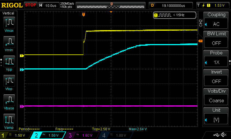
And here at the same horizontal timing as the graphs from the first test.
It’s still ramping up, but much quicker without the mosfet load. It only takes about 40uS now.
Interesting, maybe this is another situation where an intermediary transistor or small fet could help turn the big power fet on quicker?
Maybe, but I’m not really interested in that solution. The 7136 is a very large component already and is intended to drive an FET directly.
There are other ways to achieve this which do not involve the 7136. I’ve always intended to work on using an op-amp based linear driver but got side-tracked by what appeared to be a ready made solution in the 7136.
On the first page of this thread I determined that we needed a better FET, one similar to the DTU30N02. With an FET like the DTU30N02 this would be a decent driver. Without an FET liket hat the driver is not so great and I do not intend to pursue further development of it.