^ mine was connected to that one too when I first got it. By connecting to the other location, I went from 1.6 amps to 2.2 at the tail (using unmodded dmm). It worked perfectly with that and the pencil mod.
Might have shorted the emitter solder points to the reflector, usually when you loose all modes and stuff get’s hot it’s running direct drive
Ok. I Just tested mine, messured tail cap 1,7A and took it apart. Haven´t decide what to do with it yet. I have done one reflector short cut and on that one it was the 3 leged mos fet that went to haven. Learning by misstakes ![]()
Wow, that is some picture. Really great macro shot. Wish I could take pics like that.
I'm with you. Nothing obvious appearance wise on the driver. Of course that doesn't mean the more complex components didn't fail. Have you verified the tail cap switch is still working? You know, connecting with a screw driver or paper clip.
You could totally by pass the driver to make sure everything works. DD with one cell won't hurt an xml/xml2 on copper.
EDIT: of course be careful in case you have a short somewhere. You want to be able to disconnect the cell real fast if needed.
Do you own a DMM? I will help you troubleshoot if are willing to take some measurements.
Also, please post a macro of the LED emitter.
Thanks ImA4Wheelr, its not a true DSLR, its one of those fancy digital cameras that just look one ![]() I’m actually not familiar with bypassing the tail in that manner. Is this the same as using a DMM to touch the battery and the side of the battery tube? Do I just lay a screwdriver across the battery and tube?
I’m actually not familiar with bypassing the tail in that manner. Is this the same as using a DMM to touch the battery and the side of the battery tube? Do I just lay a screwdriver across the battery and tube?
I did a bit more playing last night, seeing if I could fix my other F13 by removing what looked like a bad resistor and using a piece of paperclick to bridge the connection. It ended up making no difference… That one pulls only .04-ish amps…
When I finished messing with that one I put *this *one back together. (I’m going to confuse you guys…) But now, I get no light!! Ugh… The tail cap and tube works fine on the other light, so I don’t think anything is messed up there. (This light, was pulling 1.2 amps with the single mode before it stopped working).
Hi Wight, thanks for the offer; I appreciate it. Even if I did fry something to the point of no return, I’ll sure learn alot from you guys. Here’s the emitter (click for full size):
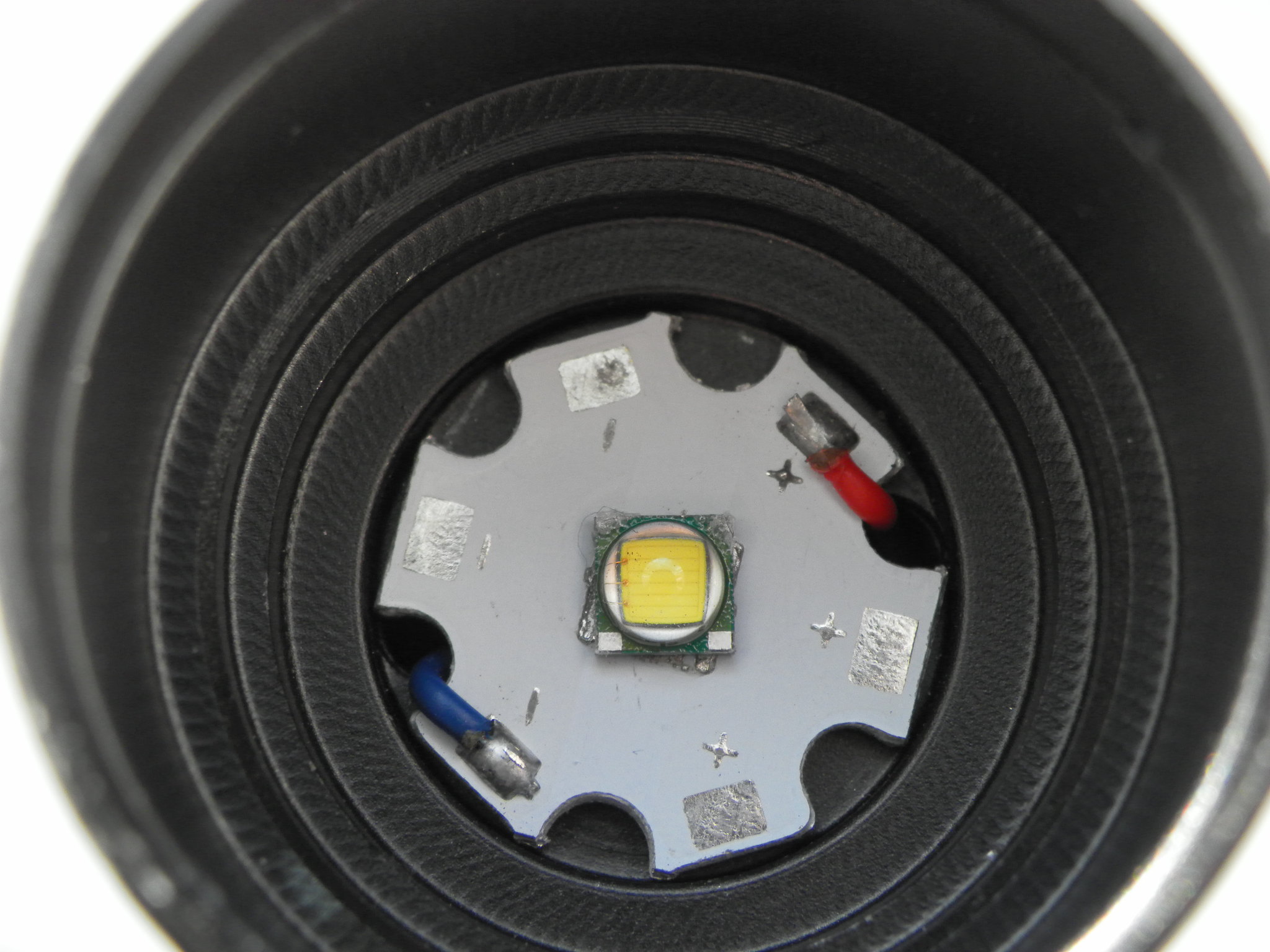
The LED has twisted counter clockwise on the MCPCB. Notice the traces under the LED are showing at an angle? That’s definitely a problem!
Yep, looks like a classic case of an overheated led that’s melted it’s own solder and shifted while you unscrewed the reflector. Best to never unscrew the bezel on cheap lights while they are on.
Other than that the emitter looks ok, so it might still be functional. You could try to reflow the led back into place…or just ditch it and get a new one on a nice copper MCPCB. ![]()
Mystery solved ![]()
I agree with kwarwick and LH. The emitter's thermal pad is probably shorting the + and - pads on the base. Easy to fix. Just remove the base from the light and heat it until the solder melts. It will likely reorient on its own, but you may need to nudge it. A hot air gun from underneath is my preferred method because you can remove the heat instantly (less heat stress). If you have a copper base, this is a good time to upgrade the base.
I agree with LinusHofmann that the emitter is probably fine. You can test it with your DMM after the base cools.
TyBreaker wrote:
Do I just lay a screwdriver across the battery and tube?
Yes, you got it.
EDIT: Looking closely at your emitter pic reveals a potential problem. It looks like there is excess solder on the + and - pads under the emitter. It looks like the emitter's thermal pad may not be in contact with the thermal pad on the base. That would have caused the unsoldering that you experienced.
Good job folks. This is a perfect example of the importance of showing pictures.
That said, who knows whether the emitter being spun is the only problem at this point.
OP - You haven’t mentioned an intention to add thermal paste under the star. You must do that. Besides that, I’d go with the suggestions above to reflow. Take a look at this video to get some ideas. Old-Lumens - How to reflow a led onto a star As ImA4Wheelr suggested, you may want to fully remove the LED from the star, wipe the star clean, add solder again, and then put the LED back.
Wow, I must not have paid close enough attention to the led when i first opened it. I assumed the led was like that when I got it! Thought it was just horribly centered.
Also, I was under the assumption that as long as the led was soldered to the center, it would work. ( I’ve never reflowed, but I have a butane hot air blower that I might be able to use to put it back in place)
Wight, I put thermal paste under the star of my other f13. However, I didn’t put any under this one yet…I’ll do that too and immediately from now on with all my lights.
Actually, what I’ll do is grab an xml2 on copper and put it in. I’ll put thermal paste under the star as well and report back. Thanks everyone!!
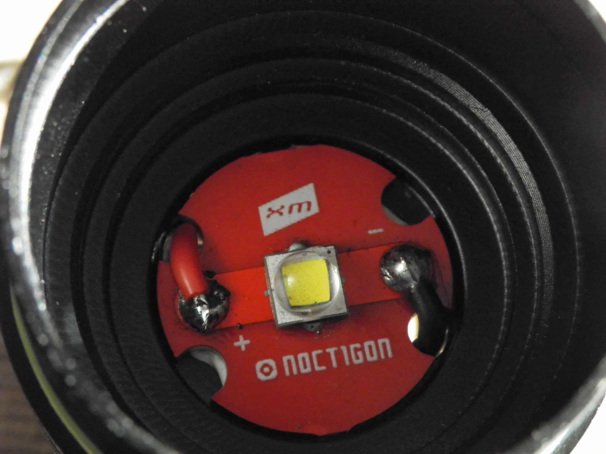
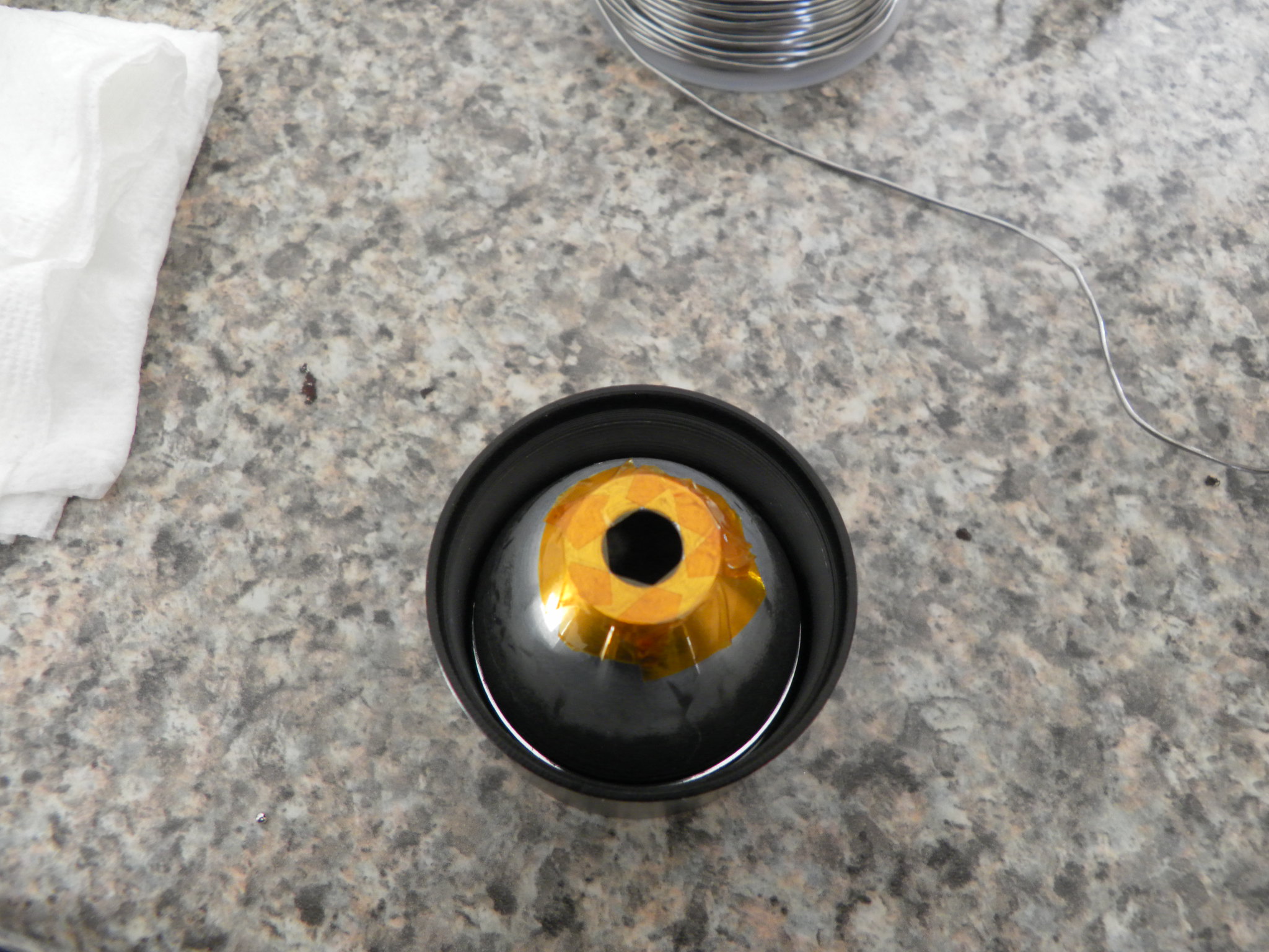
Alright… used a bargain bin MTNElectronics XM-L2 on noctigon, upgraded to 22 gauge wires, added thermal paste under star and added kapton tape to reflector.
AND?!?
And….My LED lights up again!!
But….back to single mode, 1.1 amps at tail. Guess it’s pointing to the driver being the problem again? Maybe I need to start looking for a new one?
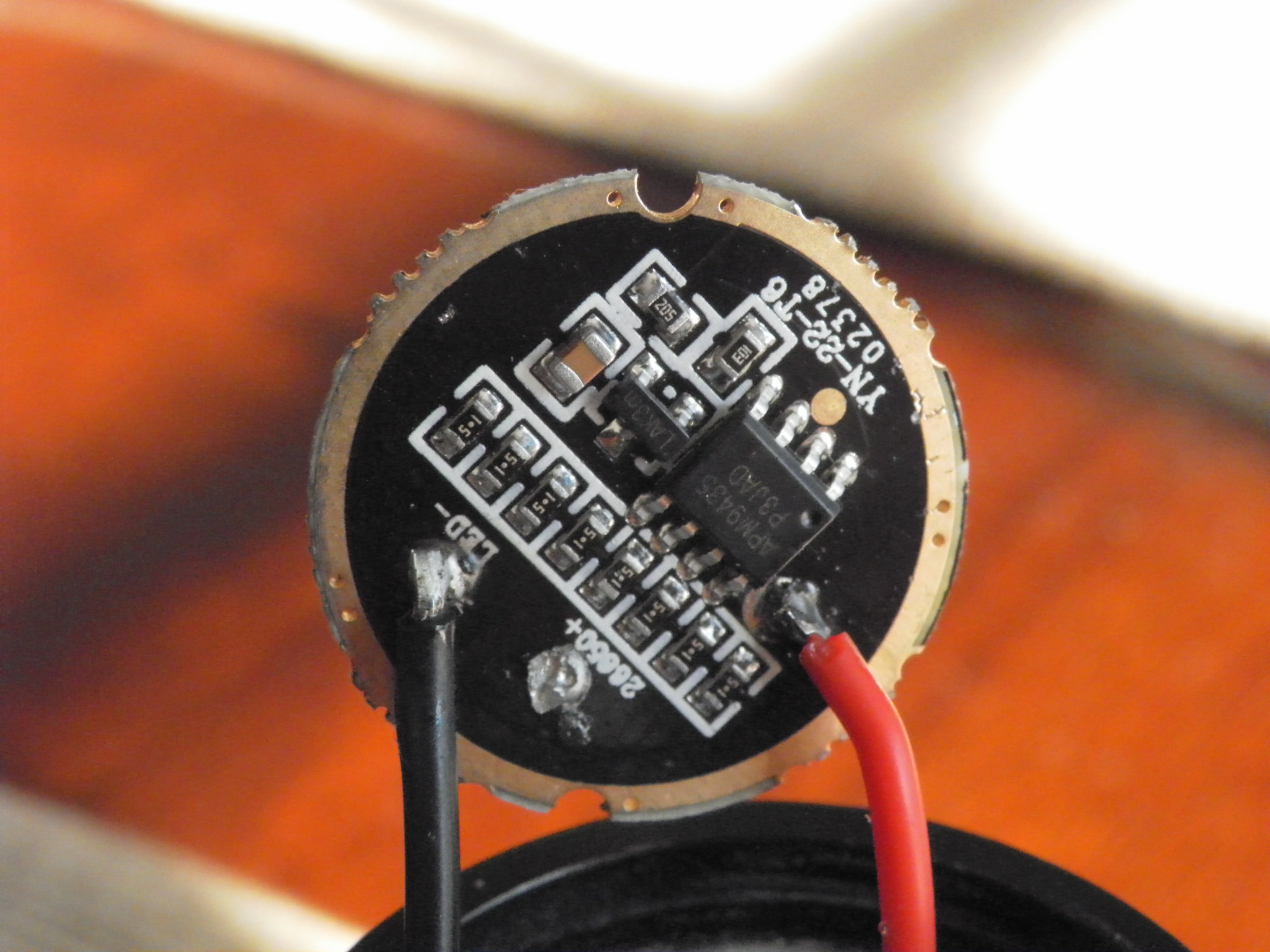
Yes. I’ve just considered which measurements to take, but there’s not much to do here. Almost certainly either the modes IC (LAKm) or the MOSFET (APM9435) is damaged.
Short Pin 4 to GND. Here is how to do pin numbering - Basics: Finding pin 1 | Evil Mad Scientist Laboratories
If shorting Pin 4 to GND does not increase current it is most likely that the MOSFET is damaged. If shorting that way increases current then you’ve upgrades your 1-mode flashlight to a higher drive current - the modes IC is probably dead.
But you get (probably) the same result (1 Mode) when you overdue the pencil trick mod on the capacitor. Cleaning the C will bring it back to normal if nothing else is damaged.
In that case the “1 mode” should be high, yes? OP does not appear to be getting ‘high’…
TyBreaker can you clarify? Has your flashlight been brighter than this at some point?
I cleaned the pencil lead off for the second driver pic, just so that you all could see that it didn’t look burned.
Before the 1 mode issue happened, I was getting all 5 modes, with the highest putting out 2.2 - 2.3 amps. It was really pretty decent for implementing such quick mods. Now, I’m getting the one mode @ about 1.2 amps
Sorry Wight, one question. To ground pin 4, do I wire the pin to the outside edge or maybe to the dot above the letters “yn” ?
The pad you asked about is BAT+, so do not use that. LED- and GND are the same in this driver. You may wire to the GND ring or LED-.
Also, please measure the nearby resistor which has topmarks “103” with your DMM. Use 20k ohm mode. You should see somthing between 9k and 11k. Significantly lower than that and it may be a problem.