I make a good living off of porting code - that's what I seem to do most of the time, lately, for the last few years... We went from custom embedded hardware (1st generation) in ASM/C/C++, to COTS (Commercial Off The Shelf) boards w/custom plug-in hardware (2nd generation) Win CE based in C++, and now (3rd generation) to Windows based Panel and table PC's in C#/.NET . Maybe 150k-200k LOC's (Lines of Code) ported along the way...
I’m glad I haven’t had to port code very much. Occasionally fix bit depth or endian issues, yes. But mostly I get to use Python and shell, which makes all that moot. Before attiny firmware, I think the last time I had used C was in the 90s. But I like C, it’s still one of my favorite languages. I’d probably like Go too, but I haven’t really used it yet.
Most of the code I write is basically prototyping anyway. Proofs of concept to decide on a good design or test potential solutions, and then if it turns into important infrastructure someone else can maintain it. Or little bits of code to break things. Or anything which satisfies the rule of three — the third time I have to do something nontrivial, I automate it.
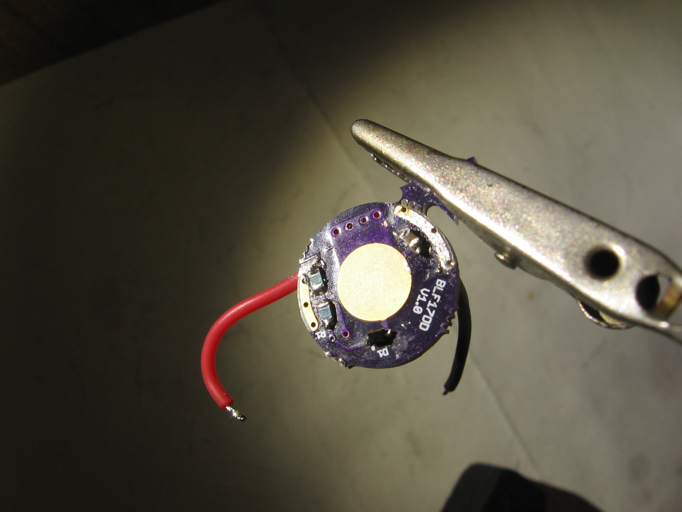
I built a BLF17DD from Mountain Electronics. It didn’t work. Positive and negative in were shorted together. I saw a line across the positive LED pad and scratched it out with my camel bone handled pocket knife, which fixed it.
+1
One driver for all needs would be superb. I have no needs for complex firmware, as long as there are no annoying blinkmodes and some different brightness compared with a direct driven turbo I am happy.
@vesture of blood
I asked in the eagle eye a6 thread why they won’t sell extra drivers and got no real answer yet…I thought that if there will be a production run of 500 anyway 100 spare drivers could be have for cheap too…like it was before in some BLf lights. Seems for me the best way.
Compared to a nanjg for 3$ a Fet driver is really non budget at 10-15$…
Yes, qty 100 is approx $12 ($1200 in advance). Even at a qty of 1000...price is $9. Prices like $5 do not come in to play unless there is a qty of 5000.
Is this Quote from itead or another Chinese ? Or from a US assembler?
Didn’t thought that this would be so high Especially for such a small one Sided PCB
No. It is from 4 other driver manufacturer's in China. The misinformation is that most think that everything is cheaper in China. The only thing cheaper there is labor. When dealing with things like drivers, we are so far down to the component level the only possible savings is in pennies and not dollars.
There is another thread on BLF where the same was attempted. One of the hurdles is and will be the money. No manufacturer starts with less than 50% down and the remainder is upon completion prior to shipping.
That is why I keep trying to tell everybody that a custom hand built individually flashed driver for 12.99 is a deal.
I’ve only got a couple of the Ver 1.0 that I can find but they don’t have that trace across the positive like that. Looks likely that there was a run (or some affected boards) that had a trace that fell on top and got under the mask and nobody caught it. Freaky.
I’ll have to look at the boards closer from now on cause I would never have found that!
I found it by debugging. It didn’t work. (With the thin wires on my battery box, I didn’t notice anything heating up.) Connecting straight to the star didn’t light up either, until I disconnected the star from the driver. My meter showed zero ohms between positive and negative. I couldn’t find any solder connecting positive and negative, so I looked and found the narrow trace. The other boards didn’t have the trace. Scraping it away fixed it. I don’t remember all the other things I tried.
I was soldering this driver and lost the 100 ohm resistor that goes in position R3.
I found one from another driver that is marked as “R100”. Is the same value?
Also have two spare “2000”, can I put one on top of the other or I’m wrong with the mathematics.
Thank you very much.
I think “R” denotes the decimal point so R100 is .1 ohm. You need 100R. In reality though, that resistor was placed as a quick fix for a voltage spike issue that was corrected by moving C1 I think.
 . Maybe 150k-200k LOC's (Lines of Code) ported along the way...
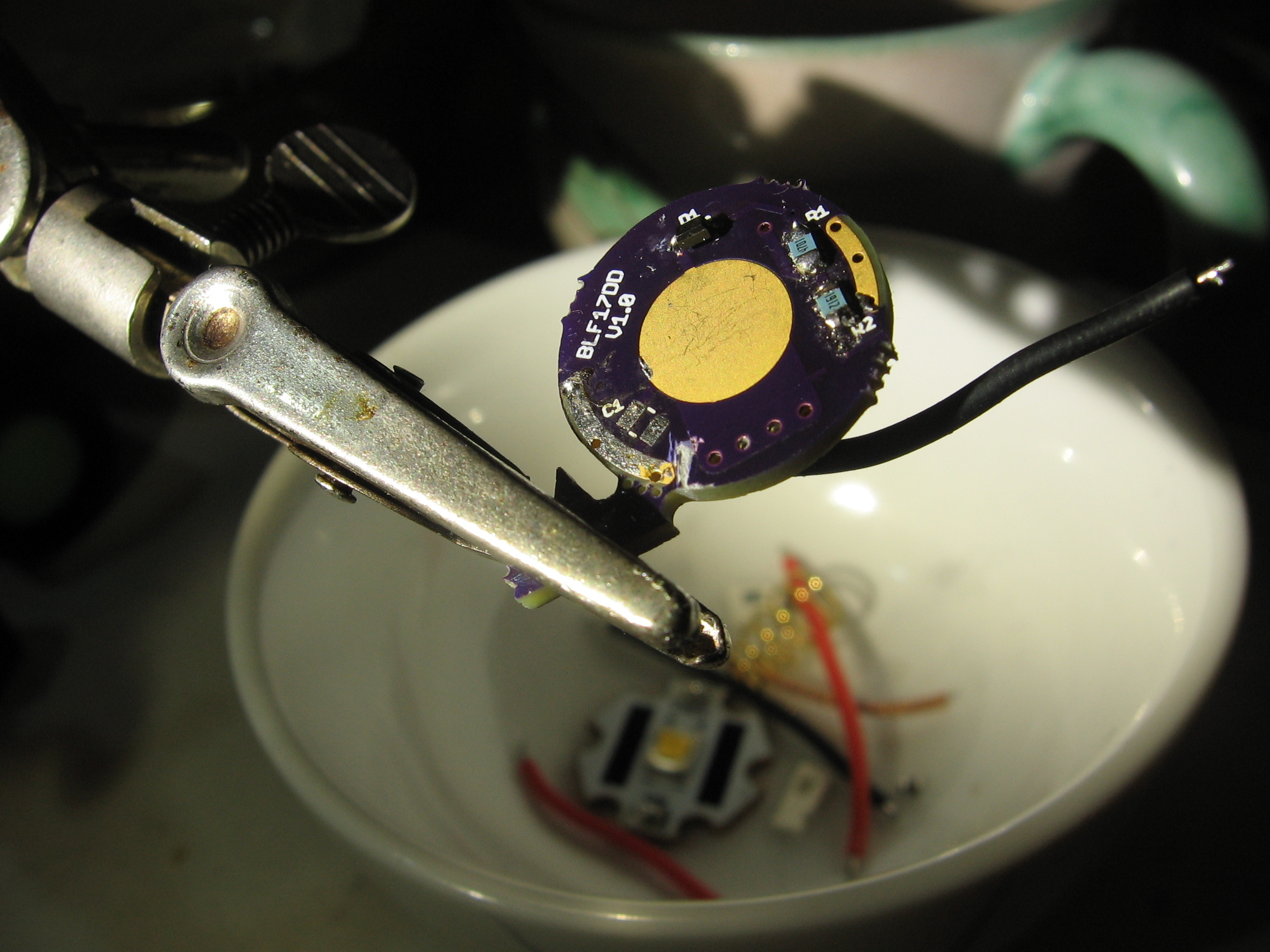
 Glad you got it fixed man.