Subscribed! I'll be modding mine soon too!
-Garry
Subscribed! I'll be modding mine soon too!
-Garry
I have one of these light on its way to me. I wonder how practical it would be to file down the base of the reflector to make it less thick. I wonder if that would be easier and as effective as putting the LED on a pedestal.
I tried filing down a reflector of one before to try get some clearence from the wire pads big I went to far and when I tightened down the reflector it pressed in the base of the reflector and is now slightly concave which is making things even harder for me! Maby you can get away with it but don’t go to far.
If you use the 32mm Noctigon, you can sit the reflector directly onto the MCPCB if you file the outer edge of the reflector base slightly to clear the LED + - pads.
Caving in the base of the reflector is actually raising the emitter further into the reflector relative to it’s focal point so I wouldn’t say it’s working against you. Per se.
But be careful you don’t try to go too far and check your hotspot at long range to make sure you’re still getting a nicely defined hot spot there as well.
A lux meter and checking the max readings at distances above 10meters is really essential for dialing in the perfect focus. I used to try and dial in focus just shining the light indoors and checking the hotspot at close range. But that can lead you towards tuning the focus for best performance at short range and actually result in worse throw overall when measured at long range!
On my Courui (with a not dedomed emitter) the slight caving in of the reflector shelf and trying to sit the reflector down as far as possible by sanding down the stock centering ring I actually pushed the emitter slightly past ideal focus. With the emitter dedomed I expect it to be in better focus again but with the dome on it’s a little bit too far forward and actually sacrifices maximum lux at long range/infinity.
And that’s without raising the emitter on a pedestal or anything like that, so just wanted to point that out.
The quest for perfection can often tempt us to go too far in some cases ![]()
Here is a little animation I made showing a simulated flashlight hotspot done by sweeping a square die emitter through a parabolic reflector’s focal point.
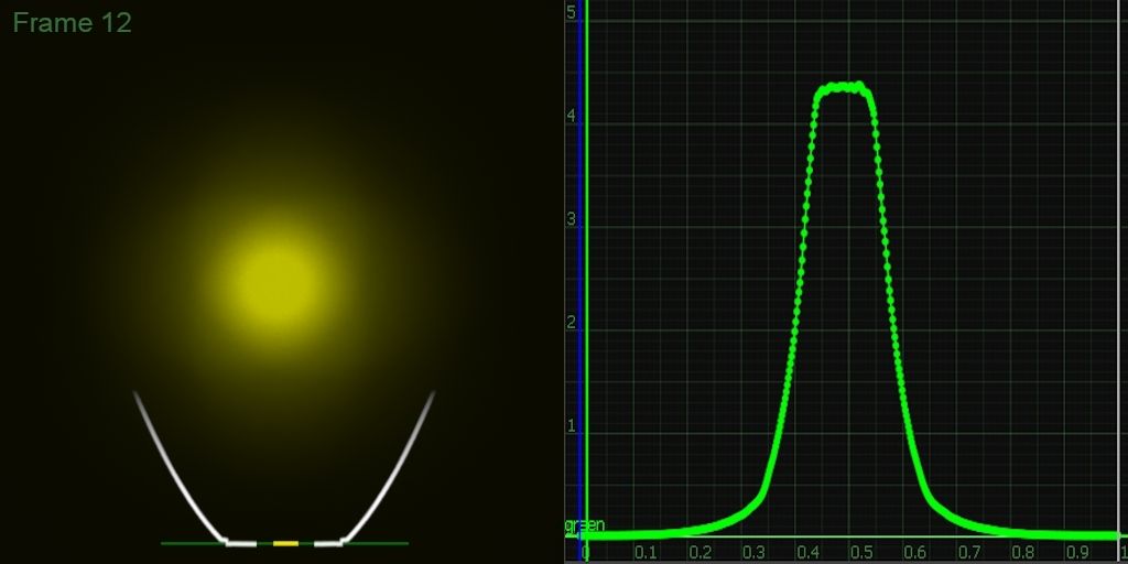
Link to Mov Video File - Download and play with Quicktime to scrub through frame by frame
The range of travel is only about 1mm in either direction past the focal point (which is passed through on frame 12-13) so not much travel at all and you can see how it affects both the hostpot shape and the max lux of the hotspot (in the sample graph).
My point is just that, once you’ve hit close to the focal point. i.e having the emitter surface close to flush with the base of the reflector it’s about as good as your going to get.
Usually the focal plane of the reflector is flush with the shelf of the reflector). Going any further forward is not really going to result in any higher throw, even if it may seem that way when looking at the hotspot on a white wall or possibly even when measuring it at closer range. Looking at these sims I can see places where the center of the hotspot may seem like it’s getting a bit brighter/smaller relative to the rest of the hotspot. But looking at the actual brightness samples in the graph you can see that as soon as you’re out of the ideal focus range of the reflector the results are always going to taper off in terms of max throw.
Also it’s important to note that pushing the emitter into the reflector is essentially shortening the reflector overall and that may explain why the falloff in hotspot brightness is more pronounced going forward compared with pulling the emitter out (even though pulling the emitter out of the reflector is effectively cutting off the total light output from the lower angle emitted light fromthe emitter. Because of the shelf rim getting in the way - that light incidentally is what makes up most of the corona around the hotspot and doesn’t contribute as much to the defined hotspot)
For me at least it’s quite interesting to see, and play around with this stuff.
Oh and just to be clear these are simulated with vfx grade software raytracers and not to be taken as anything scientifically accurate. For example I don’t believe diffraction is taken into account and of course it’s assuming a perfectly even emission angle and perfectly efficient reflector.
But that said they’re certainly proving to be a good visual guide to understanding how reflectors and emitters interact. I always wondered just what a perfectly focused XML in a parabolic reflector should actually look like and having that as a reference to dial in focus is really useful.
I’m working on a whole series of these type of simulations and I’ll post up a thread at some point when I have some more done. Hopefully other people will find them useful. ![]()
That is my shopping list, how did you know that? ![]()
Only (big?) difference is that I have installed the big copper pill I bought on this nice forum.
Waiting for some stuff to come in, I will post pictures and lux readings after that.
Greetz
Nico
cool. yeah i am waiting for that copper pill to turn up from NikolaS can’t wait. ps i am planing on piggybacking that driver. and that AR lens is so nice. When i get around to it i will post links to all those parts on the OP
that software looks like a very useful tool. I wonder if it could be used to design the ultimate reflector shapes that would have the perfect focus without any modding needed by the enduser.
A perfect shape for projecting a flashlight beam really is a paraboloid, and that’s already used in 99% of all flashlight reflectors. With a perfect parabolic reflector and a true point source of light placed exactly at the focal point of that reflector, it will project a perfectly parallel beam of light. Basically like a laser.
That said you’d have to disregard real world limitation such as leds not being anywhere close to a point source (picking a smaller emitter in relation to the reflector size helps here) and things like inevitable surface undulations of the reflector oh and diffraction properties of light also play a role.
It’s these real life issues of relatively large area sources i.e leds (not a point source), diffraction and surface imperfections and a whole bunch of other little things that cause the parabolic reflector to not do what it is supposed to do.
To get the most out of a flashlight like this though, and that’s what I’m actually interested in. It’s really just a matter of manufacturing/picking a paraboloid reflector of the right size and proportions then slapping the emitter right on the focus. It’s usually that last part that seems to stump a lot of budget chinese manufacturers. Usually it’s just laziness, or assembly shortcuts that cause problems.
The Courui is a great example. The reflector shape is absolutely fine but the stock centering ring is far too tall messing up the focus and not allowing the reflector to work to it’s best potential. All simply because it’s easier for them to clear the soldering blobs that way.
Also on some other cheap lights (I remember the HD2010 had this problem) the machining of the reflector and the resulting focal plane of the reflector is actually correct in relation to the top of the shelf, but the tolerances allowed for the the thickness of the shelf are too loose and that can sometimes require a lifted emitter to get it into proper focus.
-
I just wanted to point out that there can be such a thing as going too far in terms of wanting to lift the emitter or squishing the wiring down to crazy levels.
I did the same and doing these simulations I am now realizing I actually pushed the emitter too far into the reflector and reduced my maximum throw as a result.
There is a definite sweet spot, the same applies for getting the emitter nicely centered. That can also have a big effect on the resulting hotspot.
Are you talking about the triple / quad / single xp32 noctigon? Have you used that one sucessfully? If so that’s great news. Looks like it adds the most thermal mass.
Hmm interesting, I’ll have to do mine, been sitting on the side for some months now. I made a copper heatsink - I also have the same led as yours, just needs de doming.
bump
So how many amps you pulling from the cells and which cells are you using? I'm only managing 3.05A from (3) fully charged LG 4.35v cells.
-Garry
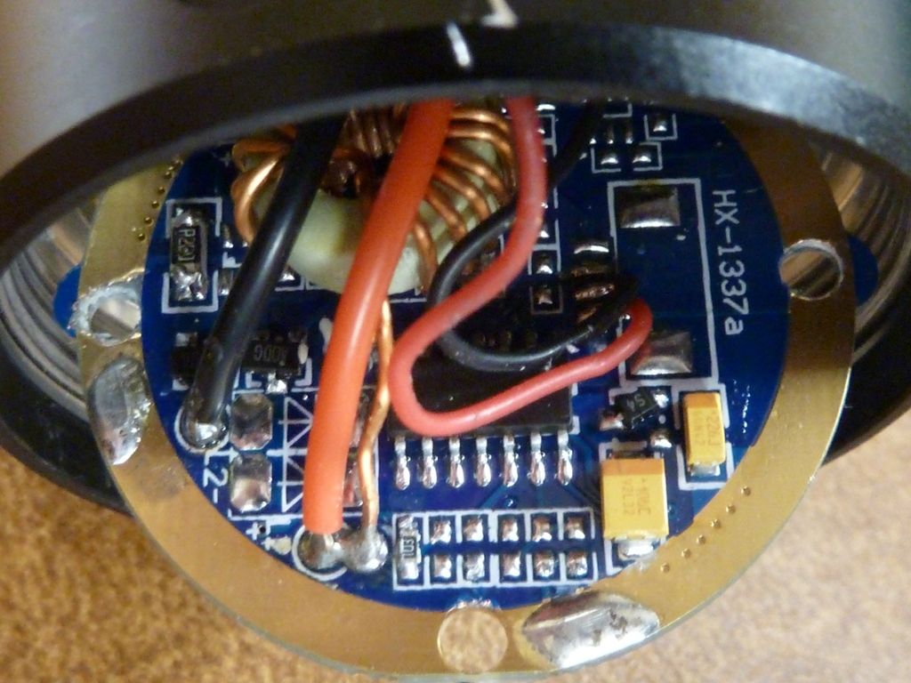
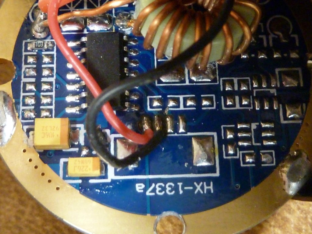
Garry - I started on CORUI D01 modding. I see two major issues with the D01 that must be addressed for high amps:
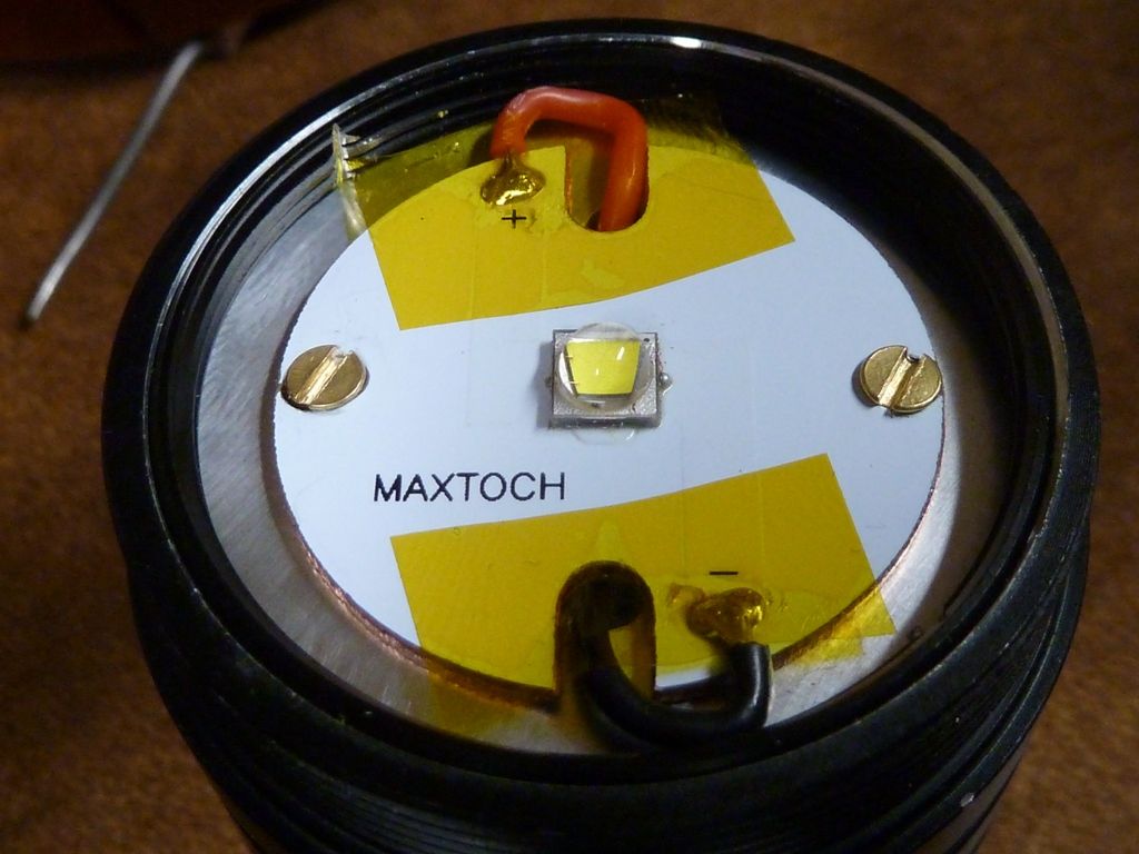
On the LED side, I used the big MaxToch MCPCB, though it's not big enough for clearance. I flipped the pill top piece, and secured it down tight with the camera lens adapter ring someone else found that works/fits perfect. Right now I'm using 22 AWG wires, lapping onto the MCPCB from the outside, not the wire cutout, but still used kapton tape. Better fix would be thin copper extensions, then I can use 20 or 18 AWG wires.
do you have any pics?
if i understund correct your solution this is what i have done in mine :


Oh boy, sorry it's been so long - didn't see this til now. You basically got it - I'm trying to recall, looks like I didn't have pics, but what I did was add wires (silicone covered, maybe 22 AWG), between the springs, like you did, but also connect to the screw thru-holes, since that is where the contact to the body is made. I recall it was a little tricky to not interfere with the screws, but what I did would totally eliminate the PCB traces. Think of where/how the electricity flows - springs to screws, so that's what I wired.
Update: Found the pics, just never uploaded them. This is how the MCPCB came out:
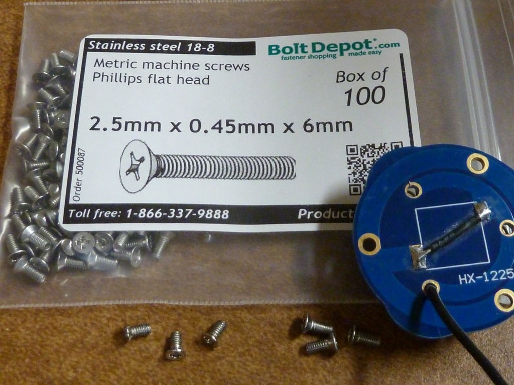
Not sure bout this one, but think these are the screws I used in place of the stock ones:
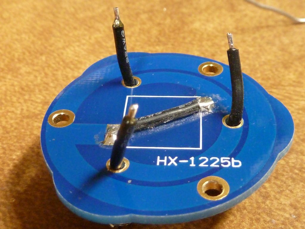
Shows the holes drilled thru the PCB, and snaking first wire:
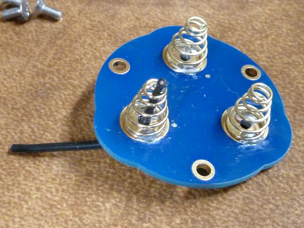
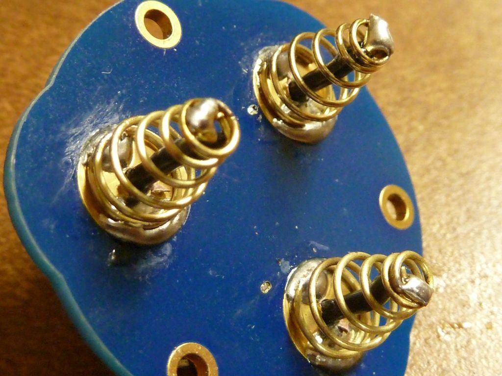
Spring side after soldered in :
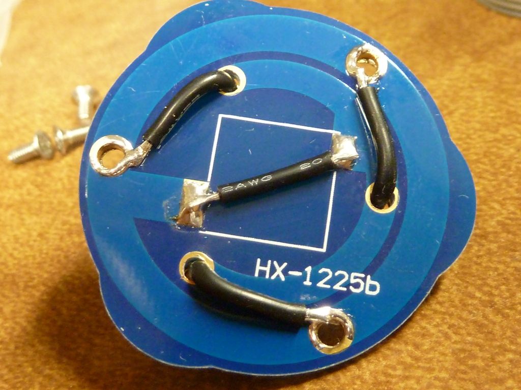
Middle wire may not be needed, but added it anyway:
End cap side soldered up:
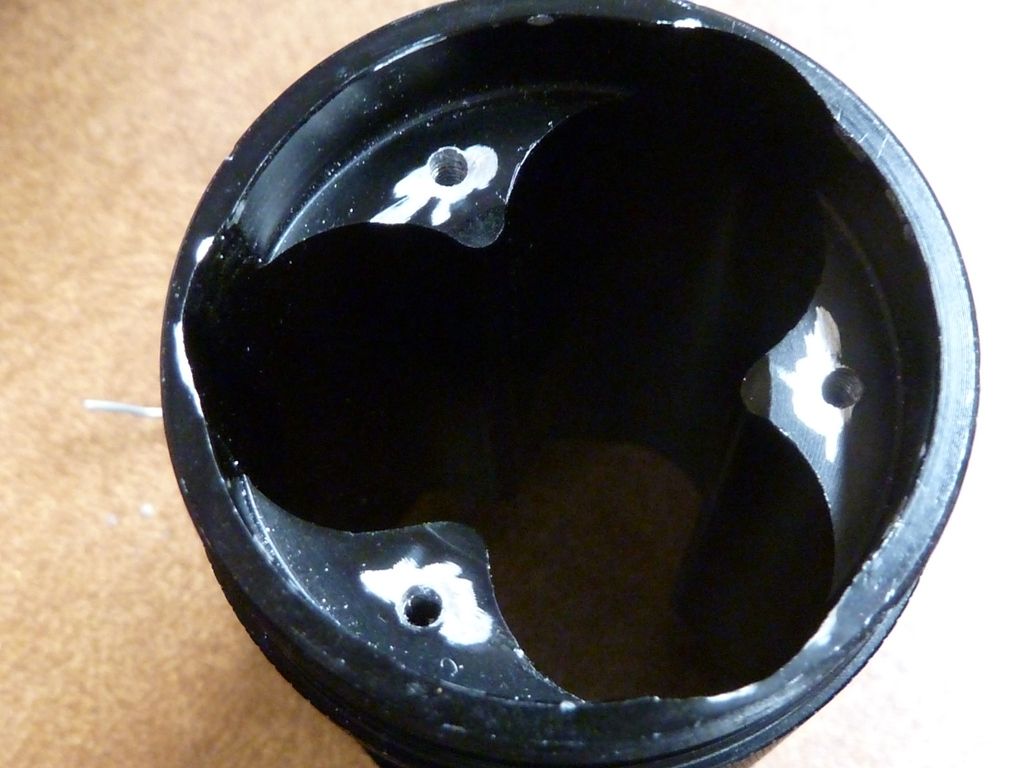
Think this was dremeled to expose some bare aluminum:
Showing drilled holes and resistor mods:
thanks for the pics.
This light has been on my list to get and mod. I think now I’m gonna bump it up and get me one here soon to begin working on. I really like these lights in the gray color. Something different from all my other plain black lights. Quick question though, do you happen to know the diameter of the hole in bottom of the reflector?