I bought a couple of blf17dd drivers from mtn.electronics last year. I want to use one now with a side switch but from what I’m reading I need the right firmware. How can I check if I have the right firmware for that without busting it?
Can you go into your order history to see what firmware is on them?
You won’t fry anything if you hook it up & bench test by grounding pin 2 to see if it changes modes.
I tried looking through my emails but I think I deleted it. So if it won’t fry anything I’ll try what you suggested, thanks.
Some firmwares were set to use pin 3 instead of pin 2 - so try both whilst you are at it.
Probably easier to just add/remove/add power to the driver on the test bench; if it changes mode, it’s not an e-switch f/ware.
I just tried powering on and off and it seems I have firmware for a clicky. Is there anyway to change this?
Only by re-flashing with the appropriate f/ware.
I’m set up to do it, but I think it would cost you more in postage to send it to me than it would cost to get another one from RMM, or even to get the gear to program it yourself.
see;
or
Oookay, new driver it is. Thanks FmC
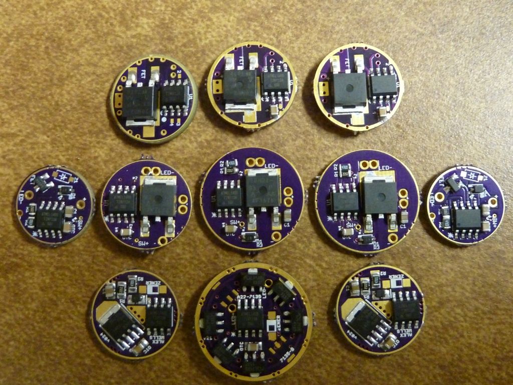
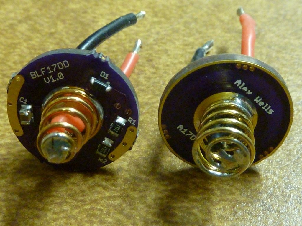
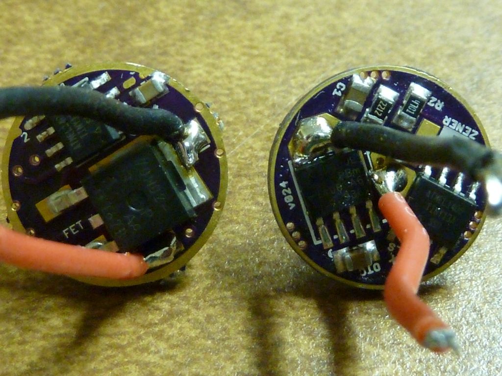
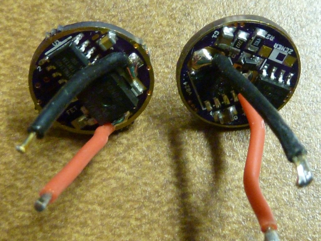
anyone has some close up shots of these BLF17DD populated?
I ordered a Parts-Set from mtnelectronics, but I have more parts than the one in the first post of this thread.
also, mtnelectronics is offline for the moment, so I can`t see any of his pictures.
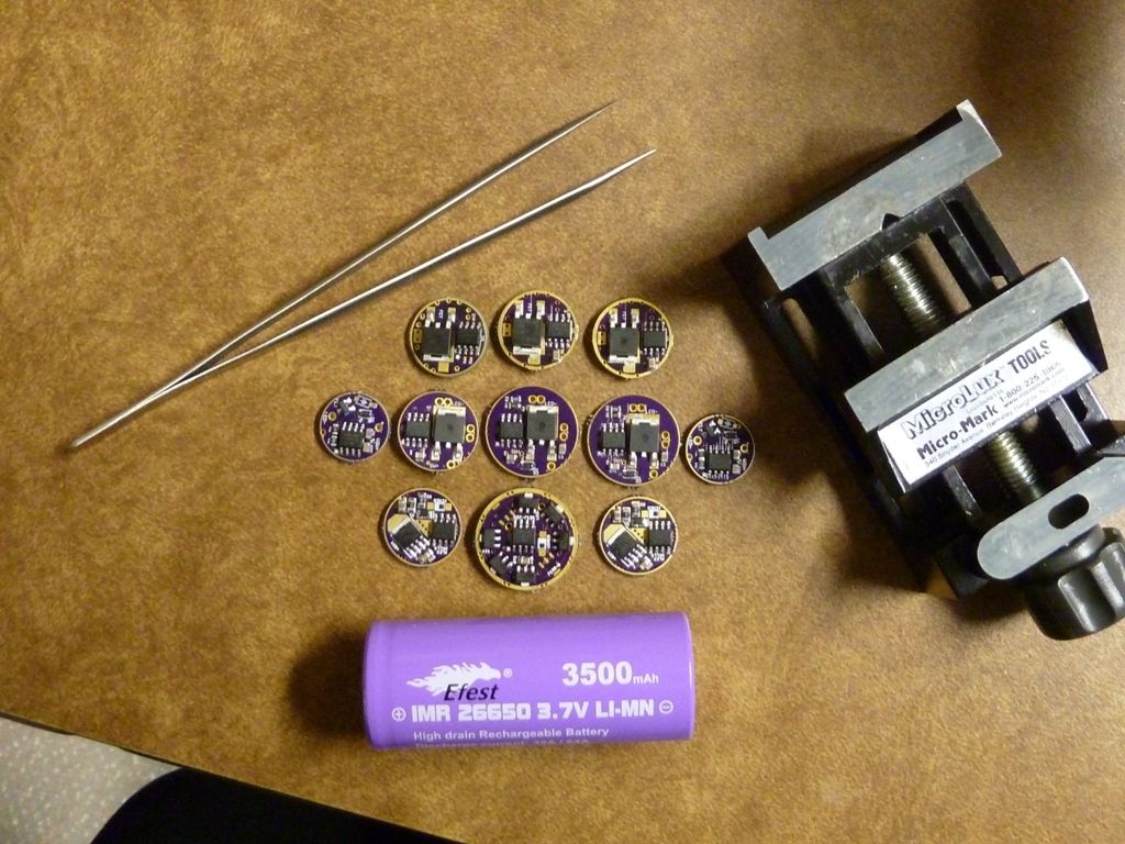
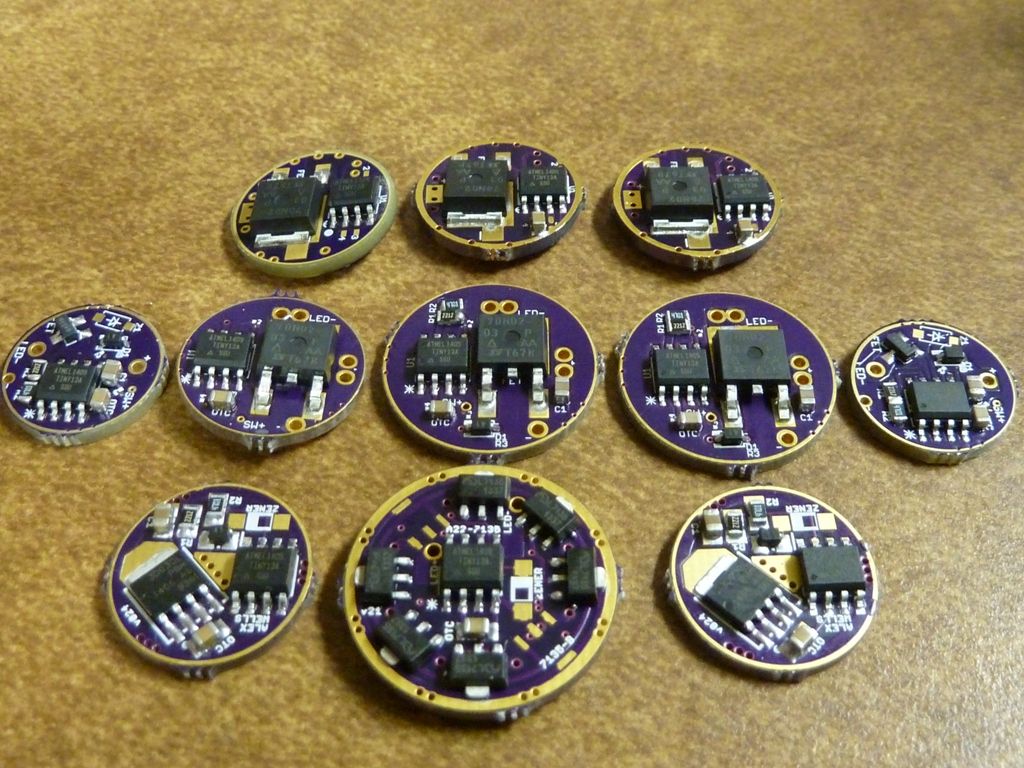
Here's some variety shots - think the BLF17DD current version is included:
Thanks a lot!
the top 3 look like mine.
now double checking all the parts.
Is C1 and on the opposite side number #4 the same thing?
I have 2 of them... 1 came in a black packaging, and the other in white with a red pen mark.
edit: my short memory wasnt working well... 1 came in white tape, the other in transparent tape
If you got a capacitor in black packaging it wasn't from me. The small capacitor goes on the MCU side and the large one goes on C1. Should have been one in clear tape (the big one) and another in paper tape (the small one).
Oops, looks better:
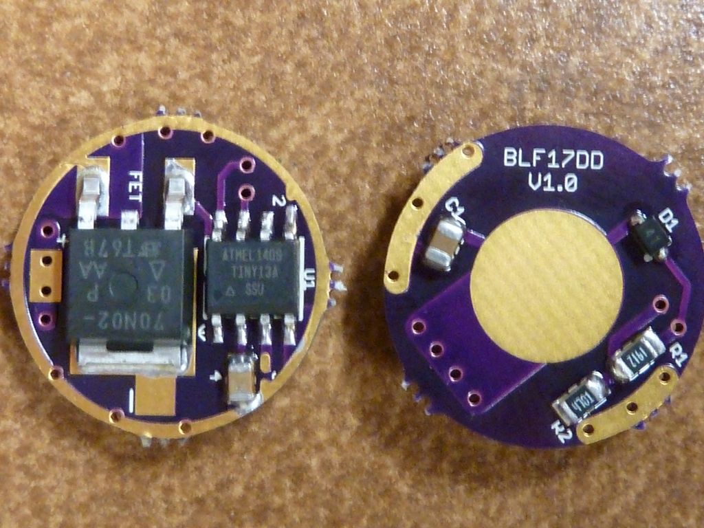
"C1" is the common cap of 10UF on all Nanjg's, while #4 is the OTC cap - lower value. You need OTC support in your firmware to take advantage of it. I like the "noinit" firmware versions floating around which makes the OTC cap unnecessary by using the "brown out" detection capability of the MCU.
you`re correct... even my short memory didnt work.
I have 1 in transparent package,and 1 in white... the transparent has a red pen mark.
(I see you call it tape,I wasnt sure what to call it)
Thanks guys!
Nice shots Tom E let alone drivers. I admire your abilities.
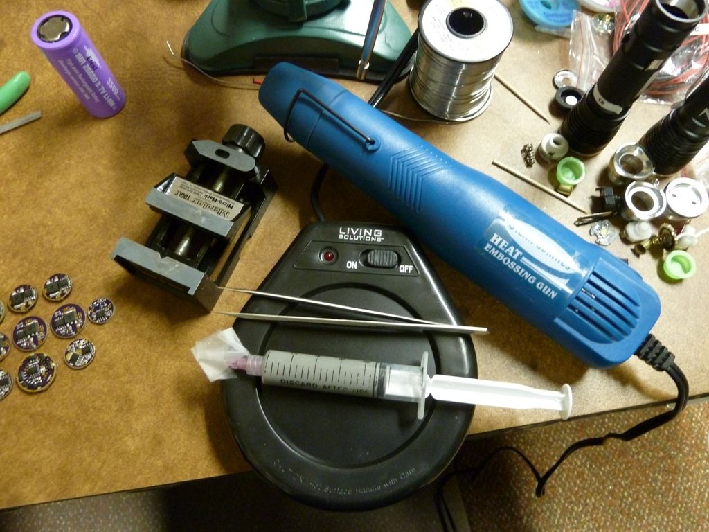
Thanx! Not bad for a reflow station that consists of a coffee mug warmer and an embossing heat gun  .
.
I bought a similar embossing gun to yours when you first posted about it and have not looked back reflowing leds. I'll have to post up a picture later how its set up. How do you use yours?
It's not my idea btw... A friend of mine set me up with this stuff - he's an EE by trade, but sort of software engineer/super hobbyist - rockets, RC's, ham radios, etc. He's like a lot of us - just a big kid play'n with his toys .
What I do is get my mug warmer up to temp, sit the board with the solder paste and parts on there for like a minute to warm up, then go over it carefully, but keep the hot air gun moving, usually pretty close, an inch or two. The paste goes thru cycles - watery first, then dries out and hardens bit, then some bubbling and smoke is a good sign you are getting close, then finally we get liquid metal...
Usually things go well, but sometimes I get parts float'n around, blown off, and even had caps stand up on one end?? Weird things can happen...