I don’t have many spare parts. The only diodes I have are LED’s, SS34 schottkeys, zeners, and the reverse polarity diodes used on all of wight’s drivers.
You could use one the zeners you have, just in the forward direction (rather than the usual reverse for zeners), its Vf will be ~0.7V just like a standard diode. Obviously the reverse voltage will be whatever the zener is rated at, but it won't matter as it won't see any reverse voltage.
Just a thought...
Do you think the standard reverse polarity diodes would work the same way?
Reverse polarity diodes are most likely Schottkys, too. You want a forward voltage as low as possible with these, something Schottkys deliver (~0.1…0.2V) what makes them unsuitable to get a notable drop in voltage. But the zeners should work as Crux said.
Ok. I’ll give the zener a shot when I get the 20mm boards (oshpark marked them ’shipped” today).
I was hoping to use the other ones because I have plenty of them, wheras I only have 2 zeners left.
EDIT: I want to save my zeners, and I’ll probably need more than one, so I just ordered these.
Yep, those will work fine.
Thanks for the tips guys. It’ll make this idea even better. Now there will be no worries about over-draining cells.
I also updated the OP to make it easier for others to try this.
If your planning to run two in parallel could you set them up with two different colors that go off at different voltages. Maybe blue down to 3.7V and red to 3V.
Hmm how do you think an rgb led would behave?
If it’s separate IAD ( individually addressable) dies then maybe it would work but then they would be all in one place. 3 - 0805 smd’s 120 degrees apart might be nicer but all you need is one or two voltage settings. I have a bunch of SMD LEDs I bought for a similar project using a quad opamp but my ideas seem to have short expiration dates.
The green and blue led would die off at about the same voltage, but if you place a diode before the blue one the voltage spacing between r g and b may be useful.
Exactly, set them up so that battery decay turns them off one by one.
The voltages for one red/green/blue are about 1.6/2.0/2.5 V for cutoff - if they are all in parallel I would add 1-2 diodes to them in series (+1.2V for two) and you get ~ 2.8/3.2/3.7 V indicator. Or one red in series (+1.6V).
The really useful voltages IMO are ~50% remaining, ~20% remaining, and 'please recharge' . So that would be 3.85V, 3.6V and say 3.0V according to the graph below. You'd have to play around with colour leds and diodes to find out how to get there. I might have a go at that, sounds like fun.  And then make a new version of the switch board with a lay-out that accommodates the circuitry, when a small Omten is used it will certainly fit.
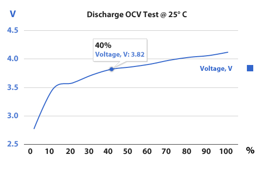
(the picture is from battery university, this should be a typical li-ion cell, voltages are resting voltages, not under load)
The 20mm PCB’s were delivered today. They look good, although the slots are not present in these. The extra diameter should still make it possible to use the larger omten 1217.
Build thread for my S8 should be posted later today
Will it be similar for an S3 tailcap? This is mighty cool I’d say! BLF is great for this kind of stuff.
As far as I know the S3 switch assembly is identical to the S8
Here’s another wild idea: what about incorporating a light light sensor that only turns the led on when it senses darkness?
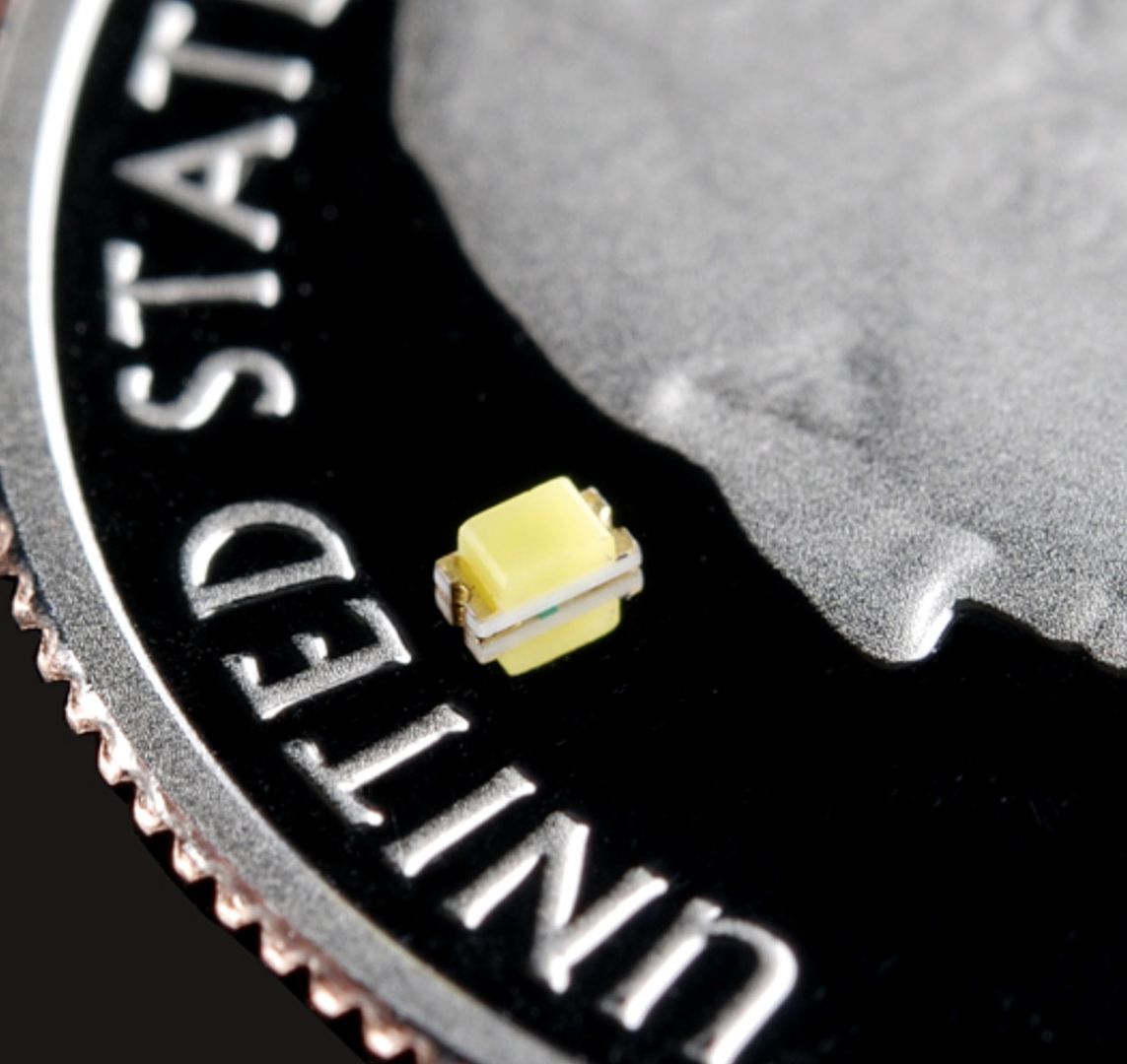
I apologize for being away and not responding to the thread for so long. Pilotdog, the LED’s that I was suggesting are super duper tiny. They give off low light but have a high forward voltage of 3.7 v. The advantage of their size is that you could have more room under your switch cover. You would have to reflow it to the PCB board you are using.
You could easily fit 3 different colors in there for different voltages. That or go for one of those 5050 size RGB LEDs.
I bought some 0603 sized led’s to try as well, but I’ve found the DIP size much easier to work with. The issue is that the retaining ring in the tail would block much of the light from an smd led, whereas the leads of the DIP type allow it to be put on the other side of the retaining ring, right next to the plunger.
Also, the 0603 size is sooo hard to see. I had trouble seeing which side is up and which end is pos or neg. I wish I had at least ordered 0805 instead.