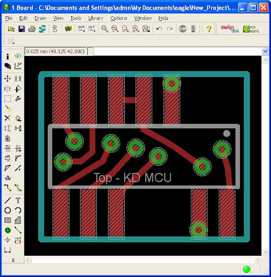
Those yellow crosses over the vias are not desirable, at least not when I do my boards. They might not really matter, but they are an error indication from Eagle. If you have the signals routed correctly, these shouldn’t show up.
Regarding design rule checks, many people don’t do them at all. They do generate a lot of errors that are of no real concern, like the overlap in your last post. It’s OK to put a via directly under a component leg like that, but eagle flags them as an overlap error. As long as the signal is the same it’s no problem. Another error of no real concern is when vias of the signal are close but not under a leg. You might get a clearance error. Once again, if the signal is the same it is of no concern. Stop mask errors are also no concern. You get them when there is white print from a component that crosses exposed copper, and OSH Park (I guess most other manufacturers too) don’t care, they do not put white print over exposed copper.
Personally I always do design rule checks. I do them once I’m close to the end of my design and I go through each error. The errors I don’t care about I approve, and then they don’t show up in the list any more unless you move the component or trace that caused it. It doesn’t take much time to analyze and approve them, and by far beats the headache of having missed something. I’ve been saved a couple of times when the DRC found sloppy mistakes I didn’t notice myself.
Download the manufacturers DRC files. Eagle’s default design rules are not the same as OSH Park, like drill sizes for vias for example. If you’re going to do a DRC you might as well do it using the design rules from the PCB manufacturer you will be using.
I also have downloaded OSH Park CAM files for gerber generation. If I remember correctly, there are different CAM files for different versions of Eagle. There are newer CAM files for Eagle v7.2.0. I don’t use the ones Mattaus provided in the Eagle tutorial thread as I use Eagle 7.2.0.
Wow, lots of excellent info there. Thank you. It all sounds good to me. I will follow it.
Yeah, I eventually figured out the X's were bad. I was pre-instaling the via's, but only on one side. I eventually read about using the shift, mouse click function. Then did it on both sides and the error would go away.
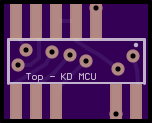
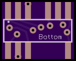
Finally got the adapter board designed and ordered. It took me a lot of time. I struggled with learning Eagle and building the parts. Parts represent the MCU’s. I could not find any already made as I don’t know what MCU’s these are. I ended up having to manually make a mirror image of the part the represents the HD MCU and then use the Eagle Mirror command to get it on the bottom side of the board. When Eagle did that, it put the pins in the proper spots (not mirror image). Anyway, I spent a ton of time on the whole process, but I can now design my own custom pcb's. That is going to be really handy for me since I tend to swap MCU's in drivers. Special thanks to Halo..., Mike C, and wight for the tips they provided.
I'll report back on weather they work when boards come in.
Here is an idea of what they have under the solder mask.
A tip about library parts, especially for MCUs (maybe a bit late). You don’t have to know the exact MCU to get a library file for the footprint, you just need to know the case. The one above looks like SOIC14. So to get one create an account at Newark Element14, find a SOIC14 processor (like the ATtiny24) and there is a CadSoft_EAGLE link under the product information:
There is a readme.txt in it describing how you make a library part from it.
Well I'll let ImA speak up, but from our PM's I've gathered that this has been a very difficult mod which has been fighting him all the way! The KD driver is nearly perfect (MTBR guys love it), but it's not a direct fit into this light. ImA has been a real trooper through the struggle though! I'd have probably given up a long time ago! I do believe he's very close to having it fully functional.
Welcome to the forum bobale. I apologize for not posting updates. I came online to post an update to Garry when I noted this thread has activity. Much has been going on with this light, but almost every step forward has resulted in complications and set backs. Tonight was yet another frustrating night and I have to admit that I am near my wits end with this light.
If you haven't purchased this light yet, I recommend you don't purchase one if your intention is to modify it. The driver is not mod friendly at all. It seems to have been built to barely handle the current it delivers stock. It is also 3 dimensional which creates all kinds of complications with reflowing and even just soldering components. If I do successfully mod this light, I don't think anyone should try to replicate it. I was entertaining modding another one of these for myself but I have decided against that a ways back. Besides the driver, the light itself is very compact and has very little "elbow" room for heat sinking. For that reason, I think a custom made copper heat sinking solution is the only real way to extract the heat to the small exterior of the light that will quickly overheat if not in motion. The tight space appears prohibit piggy backing a different buck driver.
Sorry for all this bad news. If you have purchased the light, I will gladly try to coach you through modding it. Just understand that it's a risky ordeal with a good chance for failure. I suggest keeping this one stock.
Thanks for all the info. I haven’t bought the lamp yet, but I’ve ordered one for my MTB riding friend. He doesn’t mind the stupid modes, but I do and that’s why I’ve wanted to mod it in the first place.
I’ve experimented with few different handlebar lights, and I really like this flood-throw combination in one lamp. But, if this HD-016 thing doesn’t work out, I still have my two MJ808E clones, one with regular glass lens, and one with Action-LED wide angle lens, so I guess this combination can also work good offroad (not yet tested on a trail).
If you're not already familiar with it, there was a recent group buy on the "real" Yinding (Gemini Duo clone) over at mtbr.com which is available in neutral white or cool white. The KD driver fits and it also accepts a range of different optics. Has good thermal contact to the emitter board, but not much mass to it. There's also a Nitefighter BT40S on ebay which is a 4x XP-G2 in neutral white. I just picked up the lighthead only "on sale". Some "good" inexpensive options for you, though neither has the flood this one has.
Part of the problem may be that this is a very ambitious mod. We are trying to graft on another 14 pin MCU that is vastly different. We are also trying to keep all the features such as indicator lights, voltage monitoring/protection and thermal monitoring/protection. This has forced me to modify circuits by cutting traces, adding wires, and such. Oddly enough, the extra features appear to be working fine (haven't thoroughly yet). It's the buck drivers that are giving me hell. I think the FET's have been overheating and frying. They are very small FET's and have very thin traces connecting to them. So any heat that generates, stays in the FET. I've tried harder FET's without success. I'm now trying larger off-board FET's but am having other issues now. The driver board that has the 2 buck drivers is approaching a state irreparable deterioration due to all the reflows and soldering.
If you end up finding your self wanting to mod one of these light, I think you can successfully do so if you go for less functionality and don't try to increase current to the emitters.
It's also possible that I have damaged something that is causing all this grief. I'm still trying to figure out what is wrong. If/when I find out, I will report it.
I don’t really care for thermal protection as I always dim down my light when I slow down or stop. I planned on leaving stock MCU for voltage monitoring, as I can’t really be bothered with voltage dividers and endlessly tweaking the circuit to give me correct readings. If heat is an issue, I don’t mind taking the driver board out of the lamp.
Got a question for the thermal protection dabblers out there. First a very quick high level status. Last below paragraph has question.
This project has taken a lot of turns At this point, very little of the original light is left. The light is a stubborn bugger and has kicked my butt a few times along the way. We changed direction of the build several times as we thought of better approaches and to resolve problems. Much time was waiting for parts from China and I am also to blame for the slow pace of the build. In the end, we had to toss the buck driver part of the light as it continually had component failures. In my amateur opinion, the buck driver part of this light has 2 major flaws. One, too small of components and two, no thermal path to heat sinking.
The good news is that the linear driver replacing it will be much more efficient and provide longer effective run time. Less regulated run time, but more useful run time. Additionally, the light should have all the functionality Garry wanted. It will also have copper innards from head to toe. Not something Garry asked for, but I could not control myself.
So here's the thermal protection info and question. The thermal protection kicks in around 130F (54C). This seems way too low. It steps down output by going to Low mode. As soon as the driver cools down to around 115 - 130 F, the light automatically returns to Medium or High mode (what ever mode it was in before step down). It's a pretty drastic step down, but it is what it is. My question is. What is the maximum temperature should I tune the Thermal Protection Circuit to but still have a little safety margin on not frying any components?
^ I guess the more important question is what is the maximum temperature Garry would like the light to reach before thermal protection kicks in.
I'm thinking that all the components can tolerate a higher temperature than that, but I would still like to hear any input members may have for the question I have in the above post.
I'm glad that the AMC7135's have built in thermal protection that steps down to 250mA because that will give a nice smaller level step down before the MCU kicks down all the way to Low Mode. Well, I guess that will depend on what temp Garry wants the MCU set at. I don't recall the temp that the 7135's step down. I think it's a pretty high temp though.
If any of you have any recommendations for Garry, I, and I imagine he, will appreciate your input. Keep in mind that this light will be handle bar mounted. So it seems to me a higher temp than what can be tolerated in hand would be fine.
I haven’t gotten around to temperature monitoring in my headlight project yet, but my thoughts are that I obviously don’t want to exceed the MCU’s operating temperature as it’s the MCU’s internal temp sensor I will be using (ATtiny84V). Having it ramp down at 150c if the MCU is rated to 125c is useless, unless you are counting on the MCU being able to fully operate at 150c. Also worth considering is when the temp sensor reaches a certain temp, how hot is the rest of the stuff? Is the temp sensor directly in contact with the host or is it taking the temp of the air inside the host?
If the goal is to be able to touch the light without discomfort, then I’d just do some trial and error as it is probably lower than what any of the components are rated for. If the goal is to push this light to the limits of what the components can handle, then I guess you’d have to figure out the weakest link and check how hot that link is at a given reading from the sensor.
Thank Mike C. My guess is Garry will want a much, much lower step down than 125c or 150c (257f - 302f). Having something that hot, even if mounted to the handlebar, will pose a safety issue to anyone around that might want to casually touch the light.
There will be a little lag on the sensor reading, but not a lot. The light is very compact and copper will conduct the overall temp of the host to a spot close to the sensor. The sensor will have some thermal compound connecting it to the copper/body.
I agree, any temp Garry decides on will be much lower than even the weakest component can handle.
EDIT:
Tried to get more accurate readings on when Thermal Step Down kicks in and when it kicks off. It's tough because I'm using an IR meter and the driver is small. Best I can tell, thermal step down kicks in around 140F (maybe a few degrees higher). Step down kicks off (meaning light resumes normal output) around 120F. Now I'm starting to think the stock set up is what I recommend sticking with. The light itself will be a little hotter before the sensor reaches 140F. That's starting to get hot enough to be a safety concern. Enough to give someone a burn, but they should react fast enough to not get serious burn.
My biggest concern is a different safety issue. That is the light steps all the way down to Low Mode while the rider is in treacherous terrain. The higher the thermal kick down point, the less thermal kick downs will occur, but the burn risk then increases.
If the rider had a helmet light on, thermal kick down won't be as big a deal. Maybe slow down a little and then switch to Medium Mode after thermal step down kicks off.
I reprogrammed Low Mode to be more than 25mA, but the driver still steps down to 25mA when thermal step down kicks in.
I haven’t really been following what you can and can not do with this driver. What kind of control do you have over the temperature monitoring? When I get around to temp monitoring on my project I was thinking about a hidden temperature controlled mode. Instead of running on highest until too hot and stepping down to low I was thinking about running it on the highest it can run for a given temperature, lowering the output gradually as the temperature rises towards the threshold.
I have no idea how practical this will be until I try it out, but maybe something like this would suite a bike light better than going from high straight to low without warning, but it seems that this would be difficult on the driver you have as it appears to go to 25mA despite the low mode is above that.
^ Our options on this light are limited because we can not reprogram the unknown 14 pin MCU. The MCU is from the KD driver for the ________ (forgot model) bike light. So all I can do is tune the voltage divider that the thermistor is part of.
In your case, you what ever options you can imagine and program. I think many folks (Including me) will be interested in your work on that front.
I see. Yeah, your options are very limited in that case. As mentioned I haven’t been following to the full. I thought that as you where going to piggy-back a 13A that you might have had more options.
I’ll make a thread about my project when it reaches prototype testing stage. Right now I only have the driver board assembled. I have a host to test it in once I get the firmware ready for field testing, but the programming is taking it’s time. It’s a dual LED type like this project, but with both a mechanical and electronic switch.
For reference, the stock Yinding light has been measured with a case temp at 150 degrees at thermal stepdown. I can concur that my Yinding the other night was pretty darn hot when I ran it on high for about 5 minutes during a downhill descent. I was fine with the case being that hot (as far as potentially burning myself goes). I would likely also add an aluminum GoPro mount (seen in that thread linked above) to another aluminum GoPro handlebar mount (like these) and have it attached to my aluminum handlebar.
EDIT - Here is a link to the KD driver being partially used in this build. The light it is intended for has been referred to as the "KD2".