Well I’m glad you got it working, but I’m puzzled why you need that low of values for the led’s to be bright enough. Where did you get these red led’s? It sounds like they are very inefficient. On both of the red ones I have made, I used 560ohm on the driver and 4.7k in the tail and it was bright enough to be clearly seen in a well-lit room. I had to switch to a 6.8k in the tail to make it suitable for bedside use. 3ma draw makes a lighted tailcap a lot less attractive.
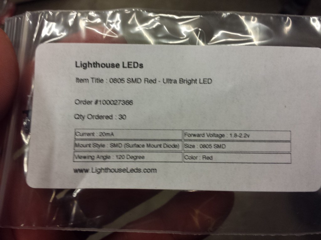
I got them from lighthouse LED’s.
It's a voltage divider -
Take the battery voltage 4.2V, and subtract the LED Vf 1.8V (or even 1.6V @1mA), this leaves 2.4V across the two series resistors, the 1k and the 560 (we'll ignore the driver for now).
2.4V / (1000 + 560) = 1.54mA, this is the current though the resistors and split between the two LED's (0.77mA each). Being in series, each resistor passes the same current. So the voltage drop across the 1k is 1.54mA x 1000 = 1.54V, and the drop across the 560 is 1.54mA x 560 = 0.86V. This is very close to enough to run the ATtiny. Either the MCU is not shutting down or this voltage keeps the OTC at 0.86V, which will interfere with memory.
You can increase the 1k, this will lower brightness, or decrease the 560 this will increase brightness. Or, for red LEDs, you may try them in series and use the 1k/560, this will increase brightness but stop working at a higher voltage, about 3.2V or so.
Because there are so many variables, driver resistance, Vf, battery voltage, etc. Calculations only get you so far, then you have to roll up your sleeves....
Edit: I started composing this before you came back with your results... I agree with Pilotdog about the LEDs being inefficient. Maybe try others?
Weird, those are the exact led’s I have as well. I see you are using the Larger omten switches, so that would explain a little blocked light, but I’m still baffled as to why they seem so inefficient.
I’ve got another red one to build, so I’ll be examining everything very closely to see if there is any difference in output and if so, why. I’m also going to sand the nylon washer thinner to try to minimize it’s effects. Honestly I’m hoping I just screwed something up (although I don’t THINK I did) because it’d be nice to be brighter AND more efficient. The LED that is, although I wouldn’t mind the same thing.
Good luck on that one ![]()
So results for #2 in red are identical to #1. With a 1k limiter and running off my power supply it’s dimmer than the steroid version running a 220 ohm with another 50 in series. I expect they’d be the same with the same limiting resistors.
Well that’s less than ideal. I don’t know what’s going on.
I’m baffled, but now that I think about it the double blue tailcap is pretty dim too (although it’s running a 4.7 or 6.8k limiting resistor). I may bump that to a 220, build a single in blue and a single in red at 2.2k and compare them all.
I can’t fathom why the single might be brighter, but the single I built in green with a 2.2k is BRIGHT.
I’ll be interested to hear what you find.
So far I have done 2 red doubles, 1 red single, 1 green single, and 1 blue double all with the 0805 led’s from lighthouse. On all of them, I have had 560ohm on the driver and 2.2k-6.8k on the tail.
Not something I’d normally consider, but do they carry a low output version of this LED and I just got the wrong one shipped to me?
With the fact that I’m getting a measurement of 5.7mA it’s hard to imagine that they’re having a problem with getting enough power.
No i don’t think they do. I’m more inclined to think we have something stealing current somewhere. Where are you measuring the draw?
I’m putting my DMM in line with the negative battery terminal to brass button and a jumper between the body and tailcap ground.
Keep in mind that driving it from my power supply doesn’t increase brightness, so I don’t think it’s driver related.
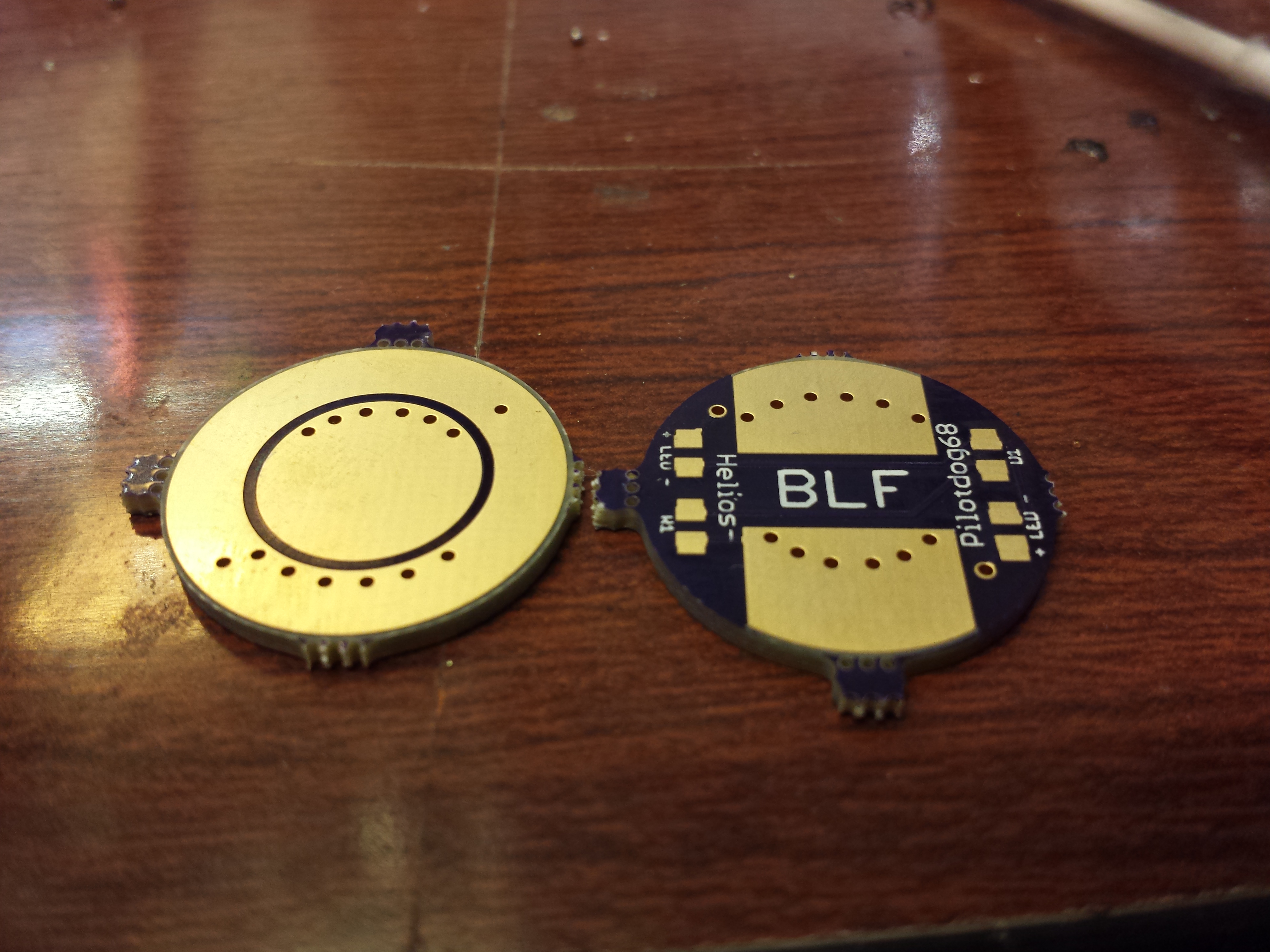
I’m staring at your pictures and don’t see anything wrong. I have gotten a board from osh with an internal short one time, but only one out of the batch was like that.
Any way to measure the draw at one of the led’s to confirm how much they’re getting? Is it possible they could have gotten overheated during assembly? (unlikely since we’re talking about 4 different emtters)
Just spit-balling here.
That’s a tall order, but I’m committed to the cause and I have some pretty pointy leads so I think I can make that happen. I’m about to get the boy from school though, so further progress will be on hold till later tonight.
So, when powered from the spring side, dim. Power applied to switch side, bright. I think it’s the damn boards.
Well at least that would explain a lot. Just looking at the boards, are the via’s all present and accounted for?
I think so. Should I try filling them with solder?
I’d check for continuity/shorts first. Its drawing a lot from the battery, so that power has to be going somewhere