I never thought of it that way.
It works fine, just different from what I’m used to as you said.
I just wanted to make sure I didn’t mess something up.
(I have a tendency for doing just that)
I have GuppyDrv on many of my lights, and this made me wonder for a minute. Since I’ve played with it for a while now, its no big deal.
I may do a basic review in a couple weeks after I get the other one in a light and get some time with them.
I dont have much by way of test equipment, so when I say “Basic review” I mean basic.
I've never done one with a toaster oven, but you're going to have to at least do part of it with something else, because it is double sided. Make sure that there are no bridges on the MCU and buck IC pins, that they all have good connections, and that the buck IC has enough solder underneath the center thermal/ground pad. I generally like to do this board with a hot air gun so I can watch and reposition everything if needed, as well as fixing bridges and adding solder while things are hot. I would rank this board as being a step or two more difficult to properly assemble than a normal FET driver.
I sent you 36K and 4.7K resistors. I'd put a little more spread between the LOW and CRIT values than what you normally would with a DD/7135 driver, unless you just want it to turn off as soon as the cells are low. The big difference here is that the amp draw on the batteries increases as they drain, while the DD/7135 drivers are putting significantly less draw on the batteries as they get low, so if you want it to step down levels before going all the way to the bottom and shutting off you need to use a bit higher LOW value.
In theory I should be able to reflow the small parts side and then do a second reflow with the inductor side. Ideally I would use some sort of SMD adhesive for one side before doing the other but that stuff is too expensive. I’ll report how it goes. Definitely won’t be a hot air gun first time around though. Which means I might fail
I’m not sure what I’m going to put this driver in though. I wanted to put it in a Mattaus single emitter p60 shell I have, but it looks like the driver area is too shallow. If I had the non-coilcraft inductor it would almost fit but with the 6mm high coil craft it’s definitely a no-go. If the single emitter shell was made to different specs it could work with the non-coilcraft inductor. And while it would fit in a Mattaus triple… there’s not much point putting this driver in there. To me it only makes sense to use a 3A buck driver to push a big 6V emitter at a reasonable rate.
thanks for the tip on the LOW and CRIT values - that is a good point that the amps are increasing as the voltage drops. We’re not in FET land anymore :bigsmile:
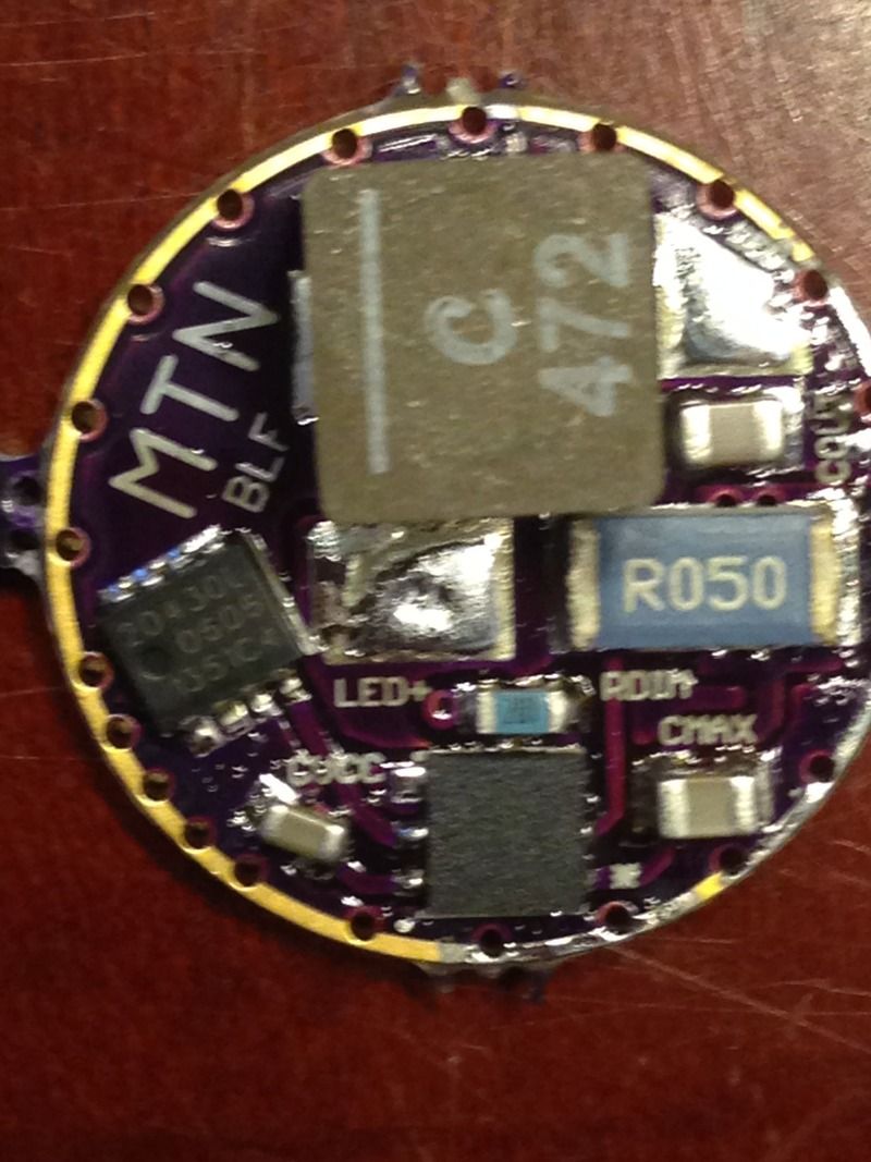
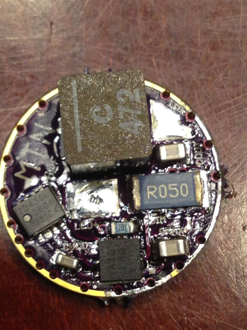
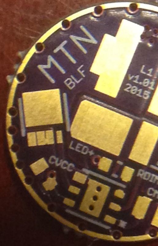
richard, can you please post some close up pictures of a built board on both sides. I have gone through and labeled each of the parts as I can.
Please check if the following is correct:
RSENSE - sense resistor
CIN - input capacitor
COUT - output capacitor
CMCU - mcu bypass capacitor
CVCC - vcc bypass capacitor
OTC - off time capacitor
D1 - flyback diode
R1- voltage divider resistor
R2 - voltage divider resistor
RDIM - dim resistor
PLDN - pulldown resistor
CMAX - Buck IC Bypass Capacitor
I’ve only done one side. I just want to make sure it’s ok before I move on. I have to talk to OshPark. Of the 3 boards I ordered only 1 is useable. The other two have bridged connections on the FET.
Keep at it and you'll get it running. Remember: no pressure on the traces if you go over them with an iron. Pressure and heat is how traces get lifted.
hey richard, I downloaded the file to have stencils made. The top stencil is just fine, but I can’t get the bottom stencil to work out. There is no bottom cream file.
Probably not. You have to go out of your way to have proper cream files made for everything, and I certainly haven't done it and probably won't. I don't use stencils. I've tried them and really don't like them.
Yes, and I think that its viability is questionable without some further thought. I built one running at 5.5A and ran it quite a bit in my UF-1405. While it didn't burn up, somewhere along the line it lost the moonlight mode level which told me that something was starting to get fried. I tried cranking up the PWM level and it still wouldn't come back. This tells me that the driver would eventually fail and that a redesign is needed if a reliable 5A+ is to be obtained. I'm guessing that the buck IC or FET is slightly fried, but I haven't had a chance to play with it since then.
I decided that these high-power buck drivers could really benefit from a 4-layer board, both thermally and to electrically. A standard Eagle license is pretty expensive, but for me my time to learn a new program (KiCad) that can do 4-layer boards for free would be more expensive than the money paid. I don't need multiple schematic sheets or autorouter, so it wasn't too ridiculous, but it still wasn't cheap. I designed a new 4-layer board with a lot more thermal transfer capability which I'm hoping will do the trick. They just shipped so hopefully I'll get around to trying one next week.
First off, good luck with the move. I hope everything goes well. Secondly, I’m very excited to hear that you think you can get it to 5A reliably with the new board and some time investigating. If you end up getting it to the point where you’re happy I promise to buy them if you put them up for sale. They’d be perfect for insane XP-G2 builds.
Just got my first boards assembled and tested from your batch with the masking issue. I think I’m going to like using guppydrive from now on, it’s going to save having so many divers around with different programming that I have to keep track of.
Keep up the excellent work you’ve always displayed here, this place truly wouldn’t be the same without you.