guardior - well if I would do the mod, I would definitely do DD in a UltraFire/Convoy C8. I used to be much more conservative in worrying about high amps, but now, I flipped nearly completely around. I find it hard to go back to 7135 based drivers now.
Here's my reasons:
it's nearly impossible to burn out a CREE LED in a DD configuration when it's mounted on a copper DTP MCPCB (assuming avg/good heat junctions to the body) - you really don't have to worry about that at all - this I didn't know 1-2 years ago. The forward voltage (Vf) level of the CREE LED's will always keep the amps to moderate levels, plus as a cell drains, the amps will naturally drop because the voltage level continuously drops, again, it's a natural protection mechanism all based on the forward voltage (Vf) of the LED .
you can set up any light for max output, then if you don't want that, use a standard cell like a Pana B to run at lower amps, or comprising will a 10A rated cell like a Pana PF or Pana BD, etc.
implement a turbo timeout to keep the heat from getting excessive
a light left on high/turbo til it gets too hot to even touch still causes no damage. Well I dunno if this is always the case, but it happened to me twice: once with a modded out SupFire M6, once with a 18650 EDC configured at 2.8A, and both times there was no perceived damage to any parts, including the cells.
Hope this helps. Again, it's all personal opinion/usgae, or subject to the target user. Certainly if I were to give/sell a modded high amps or DD light to someone not knowledgeable of the risks and has small kids that will have access to the light, I would be VERY concerned about putting that light in their hands that didn't have temperature monitoring based amp control.
Ronin42 - as RMM mentioned, amp max capabilities of the cell are not obtainable for a DD set up of one cell with one CREE XM-L2. The Vf requirement of the LED will limit the max amps. There's some really good data posted here on BLF showing the Vf levels compared to amps (for example, see post #51 here: https://budgetlightforum.com/t/-/19546). The higher the amps, the higher the Vf is, so typical 3.7 Li-Ion cells can't deliver a high enough voltage level to drive a XM-L2 at 10A, or even 8A. Highest I've been able to achieve is ~6.5A.
Well, it seems this one ended not that bad, it even has a bit higher max current using U2 1A/U2 than PSMN3R0-30YLD( like 100-200ma)
But it doesnt handle If<50ma
Testing Tom`s ramping firmware atm
As Richards said- like 5.5 amps
Simon`s T6 4C( Convoy electronics) could reach 6.5 though
Ahhh - could be. I know Simon's and yours were high amps - maybe both from older reels. The way supplies go, seems like CREE releases different bins in batch's - never seems to be a good selection available at the same time. Still the T5 4C's were older batch's - still got one. The T6 4C's came later, but still could be older than these newer U2 neutrals and U3's/U4's.
Any chance you could be talked into posting a picture of a board with the solder paste on it before the reflow? I’m starting to put together boards now and I’m still feeling out how much solder paste should actually be on there. Whatever you’re doing is the way I want to be doing it, it looks great.
The OP has a pic of what you want - I think. It's probably too much paste on the pads for the MCU. I've found I was over-doing it on those pads, and then you end up getting solder pooling on the top of the MCU pins, whcih seems it will make it difficult to program with the clip at times.
Also, I've learned if you use hot air like I do, you really want to pre-heat or heat the boards from below - the solder flows better. That's why I use a coffee mug warmer to sit the boards on when I use my hot air gun. The warmer provides bout a perfect 80-100C temp or so.
Paste? Minimum, unless you have some strange paste. If you are doing many PCBs then its best to get a sheet that is cut out where the paste is to be applied. Often made from this high temperature material also used for tapes. Brown/copper nearly see throughm, sorry forgot the name but it’s an old NASA kind of stuff You just wipe the pate over it and the paste gets only to places where it’s supposed to.
Same as soldering LEDs to MCPCBs minimum paste is enough
Do a board and see, if it looks too much to you, then reduce. If you get bad connections due to lack of solder, then add more. In general minimum paste is fine for SMD soldering.
Personally I heat up a small piece of copper 40x20x3mm with a soldering iron, the driver or MCPCB is placed on the copper. Works even for soldering stacked copper discs or copper to brass pills.
The heat builds up from below unlike when using hot air that is more useful for patching up than reflowing.
Stencils - yes, some guys use them - I don't and others don't as well. With the rate of change these boards go thru, I didn't want to invest in stencils. I've had a high rate of success doing the solder paste by hand in my small batch runs (3-6 boards or so). I know stencils is better - faster and more accurate with the amt of solder.
I've tried stencils on several different boards and for me I don't really like them--especially on boards like these that have fairly large pads and a small number of pads at that. The setup, cleanup, and mess of using a stencil just isn't worth it IMO.
That's why I like this forum: you get a good debate from differing opinions. Dale and I are friends, but anyone who has followed us long enough will notice that we often have opposite opinions about a lot of different things.
I'm planning on using four XHP70's for my DIY comp build.
If I were to piggyback 3 or 4 FET's on the same board (Older v1.0 type board, DPAK-2 FET), will the 13a have a strong enough drive signal to operate them all?
Unless you're only planning on a 100% mode level with a big gate resistor, no. We're already pushing the little attiny pretty hard switching one of them at the faster PWM levels. You'll find that the attiny will glitch out big time trying to drive multiples in the middle levels, and even a single FET sometimes.
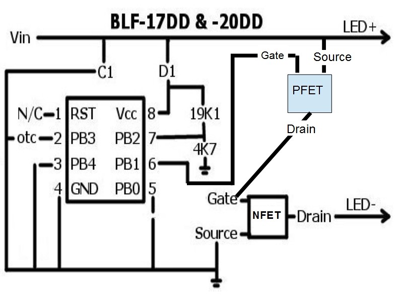
I think you could get away with a single FET for that build with a little creativity: use a small PFET to power the NFET gate directly from the 8V+ input. It will load the attiny way less and will give the FET access to higher gate voltages, which will decrease the resistance of the FET. You could also easily power more than one FET off the same attiny, if needed. You would need to basically invert the PWM values, since the PFET turns on when the gate is pulled low.
It is a crazy untested idea, but in theory it should work. I don't think you need a dedicated gate driver IC since we're switching relatively slow.
Yep. That works. You can use a very small PFET, just use one that has sufficient voltage ratings. You may also need a pull up resistor to keep it off, but you'll have to figure that out in use.