Where you seeing v044?
On 41 there is a label “dont use” already….and in fact i have some offtime issues with it( but it could be me, i am just a user)
Ahh: Alex == wight == RED  . No mention of it in the OP, but Alex's link at OSHPark goes to this thread... Weird.
The stangest thing is that there wasnt such a driver month ago when i ordered, its kinda new i am sure
So…maybe the OP is still developing in the shadows ![]()
But the Ospark page says “Shared on January 12th, 2015 05:54” :~ strange
One quick question: has anybody tried that driver with 3x AA or D class batteries? Will it hold their max Uf? Its like 4.5-4.65v….
AAs sag enough to work without issues. Some good D cells might fry an emitter direct drive.
![]() Richard
Richard
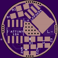
Ok, so I'm gonna go ahead and try to add my 2 cents here. I'm not really sure if this is where I should post this, but it seems appropriate since what I have is really just a spin off of the OPs board.
I asked nickelflipper to tweak the layout of this a hair for me because I needed a set of stars on the bottom to access certain functions. When doing one offs there is typically no need for this, but when you want to pre assemble large quantities of production type lights or bulbs, its really a pain to have to access the top side of the driver.
Case in point is the copper XHP-70 bulbs I make. Since the driver is crimped in I wanted to be able to assemble them and still have the option to use the "lock" function with the DrJones Guppy2drv I got from RMM.
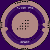
Anyway I have tested about 12 boards so far with 3 different user interfaces, including my Sport UI, the Guppy2, and DrJones Nlite. The boards and stars seem to function perfectly using the layout and the exact BOM I will post.
Most of the samples I tested used the 2S zener mod, but a few samples were also tested with the 1S set up.
Here is a link to the board at OSHPark.
https://oshpark.com/profiles/ForgivenMatt
I would suggest using the exact parts I am posting, from this seller and the brands only because it has been proven that all components and brands though they be marked the same are NOT created equal.
I also very highly recommend ordering a stencil, even if your only going to do a few boards, because it makes them come out nearly perfect every time.
Here is the BOM from mouser
For single cell driver.
http://www.mouser.com/ProjectManager/ProjectDetail.aspx?AccessID=75156464cd
For 2 cell driver
http://www.mouser.com/ProjectManager/ProjectDetail.aspx?AccessID=96d1691809
Thanks again to everyone who has contributed to this project, especially to you wight!
PS: if anyone in China is reading this please clone my board and sell them back to us fully assembled for around $2.50 each!!
+1 VOB, thanks for posting!
May I ask why you don’t have a larger via in the center to make spring bypass with wires easier?
I’ve not tried stencil’s yet as most of my driver boards are still under development and I haven’t yet settled for final versions. Do you get the stencils made from OSH Park? Or OSH Stencils?
Also, if I may ask, what do you upload as stencil mask? Looking at my solder mask layers it seems that bare copper battery contact plats, vias and ground rings are exposed. Do you need to edit them out prior to uploading the files?
Edit: Dont worry about answering the stencil question here (don’t wanna flood this thread with off topic clutter). I’ve asked in the Eagle video tutorial thread: Eagle Video Tutorials BLF Style
I’ve been asked by vestureofblood to provide the answers to these questions. So,
1) A large middle pad for wire bypass on spring is a good idea, it just wasn’t considered at the time as only a braid bypass was discussed.
2) OSH Stencil was used for the paste mask. There should be a Top Paste Mask.GTP file in vob’s zip file which in turn can be previewed in gerbv, or some other gerber viewer. Vias are covered in this design, and wouldn’t normally show up in the paste layer anyway’s? Pads in the design could show up in the paste layer but don’t, just like the vias. The B+ contact and ground rings were scratch made, so a paste layer was not automatically included, like a component part, or say a stock pad design might. If they had, then yes you could just edit them out, so they wouldn’t show up in the stencil.
Here is the OSH Stencil preview.

I think his desing is good enough, that center pad can hold 9mm spring easy
The desing offers also a larger border pad: the original one was too small and i have to always mod it in C8( for instance)
10x for the efforts about that everyone
Thanks Kent..
Is there some way I can make a shared project at OSH stencil so everyone can just click for it ( like a t OSH Park? I was able to load the file, but don't see any option to set this up.
Matt, I don’t believe that an open project setting exists in OSH Stencil, like OSH Park. So people are stuck with downloading your zip, and then transferring the paste mask file over.
Good enough :)
Can someone give me a brief of what happened in there? I never checked this thread to be honest and from the last few posts I read, I gather this project is currently ‘in waiting’? Thanks
Just discussion about the driver. People are still making improvements, but it’s ready to use.
+1. Part of the reason this driver seems like its in limbo is because the creator wight is taking a break from the hobby for a while. However there are some working versions of the driver listed, mine just above being one of them. Fully assembled drivers and parts kits can also be purchased from Mountain Electronics.
Thanks man!