Hats of to you ImA4Wheelr. What an extraordinary amount of effort has gone into this light and it works not that I had any doubts. 
Thanks for the feedback Garry and the compliment MRsDNF. I really like those trail beam shots. You must have had a late night making that happen. I have to give you credit for the light's rockability. It was your concept to combine the beams at all power levels, go 5B1 tint, AR lenses, improve the heat sinking, and to controll all that with a solid mountain-biker-safe UI. I'm honored you asked me to make it a reality.
MRsDNF, you always seem to notice the critical parts of a process/build. You are right that it was a lot of work. It also was close to not working. I just about gave up several times. Garry was good at keeping me in the game. Now that it's done, I'm grateful to him for that. I learned tons from this build and it forced me to grow in areas I tend to neglect. I really noticed my growth last night when putting the final touches on my Rook. I'm a better modder now. I also learned that custom builds are definitely not my cup of tea. I really admire the folks like you that undertake them. It takes a special skill set and attitude to be successful at it.
EDIT: How do you get the pictures scalable to the screen like that Garry?
EDIT2: Fixed cap in MRsDNF. Sorry about that.
About the pics, I use the advanced post editor and on the "appearance" tab at "dimensions" you put "100%" (or whatever size you desire) in the first box and clear the second box. That simple.
-Garry
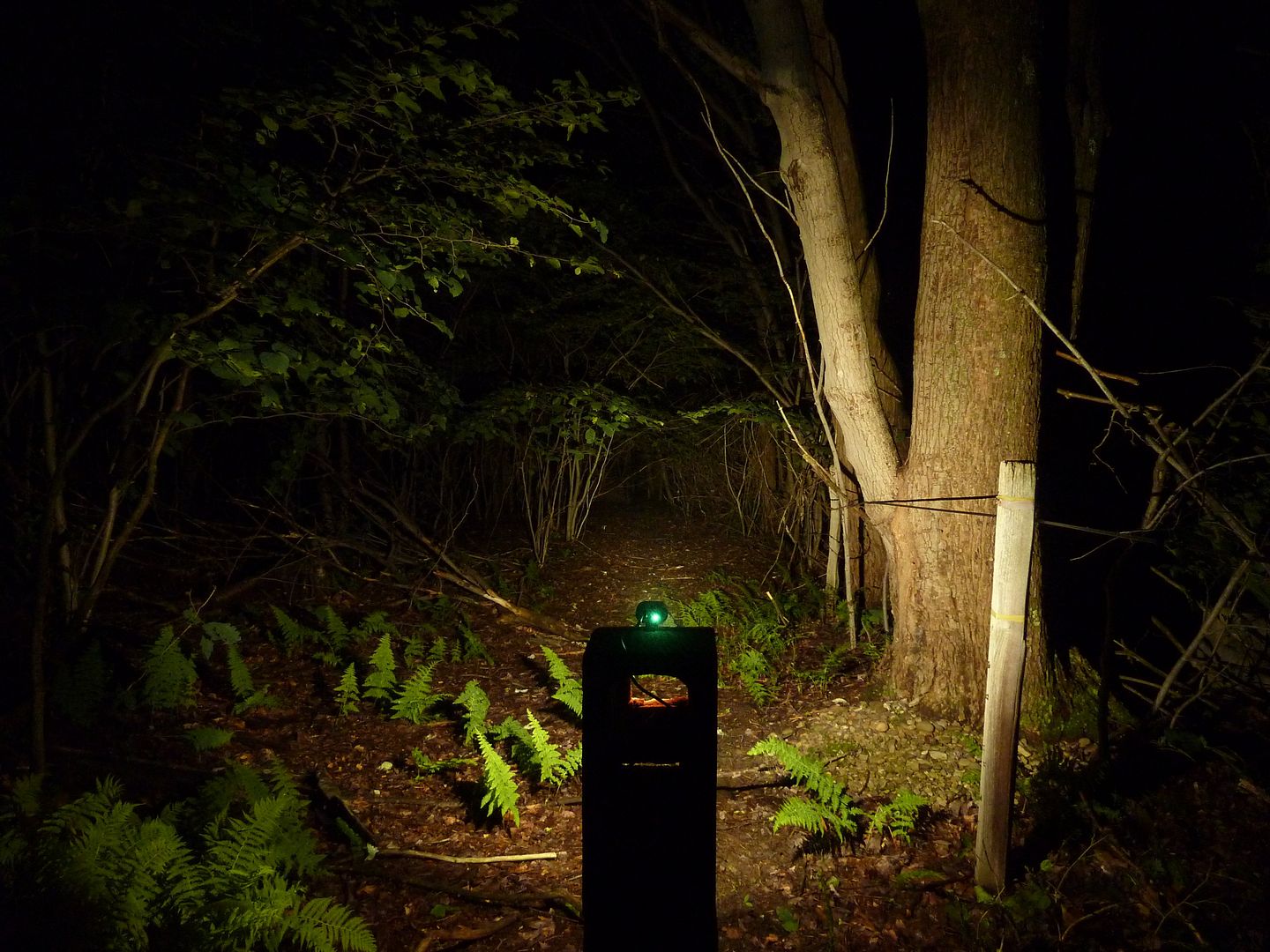
Ok, here are my beamshots I promised. I was in a rush to beat a storm coming, and didn't notice the first shot was way out of focus (I did almost get some shots with lightning strikes in the background!) Also, the original beamshots had a wrong white balance setting and appear more blue than they should (should appear a crisp cool white). My modded beamshots are with the KD driver programmed at levels 2,7, & 10 (I think low is "2", but I never confirmed that after my accidental reprogramming). Keep in mind the stock light was only driven at +/- 1.4A per emitter and now it's modded to 2.4A per emitter. Original beamshots are only with both LEDs on (no sense comparing single throw / single flood shots).
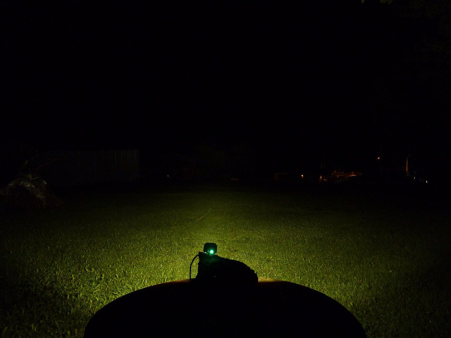
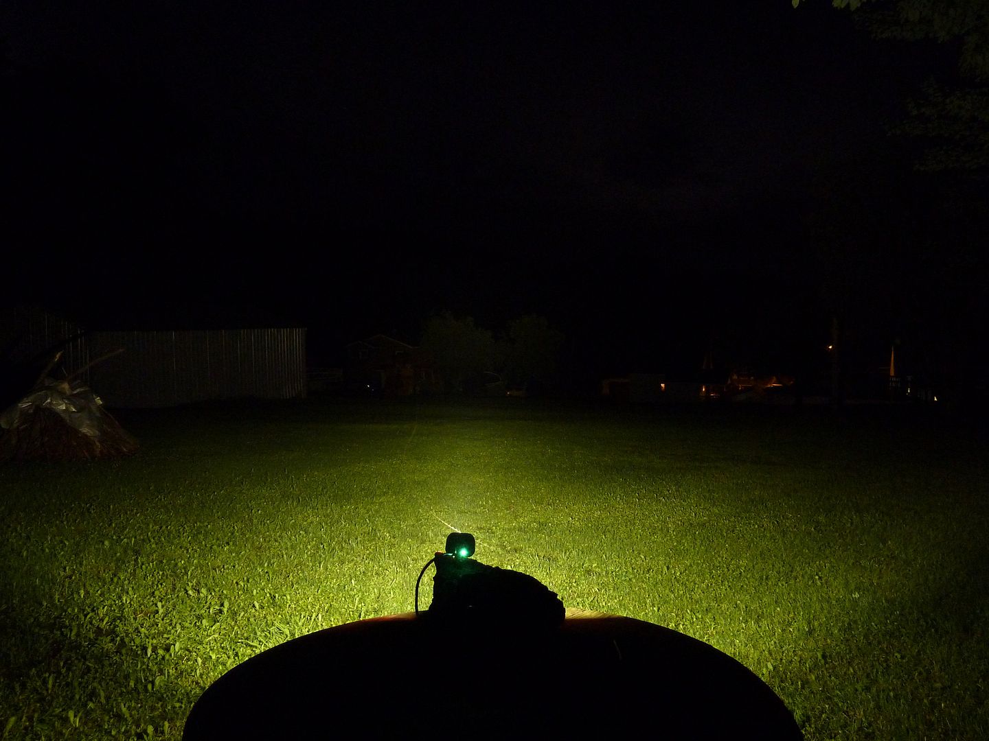
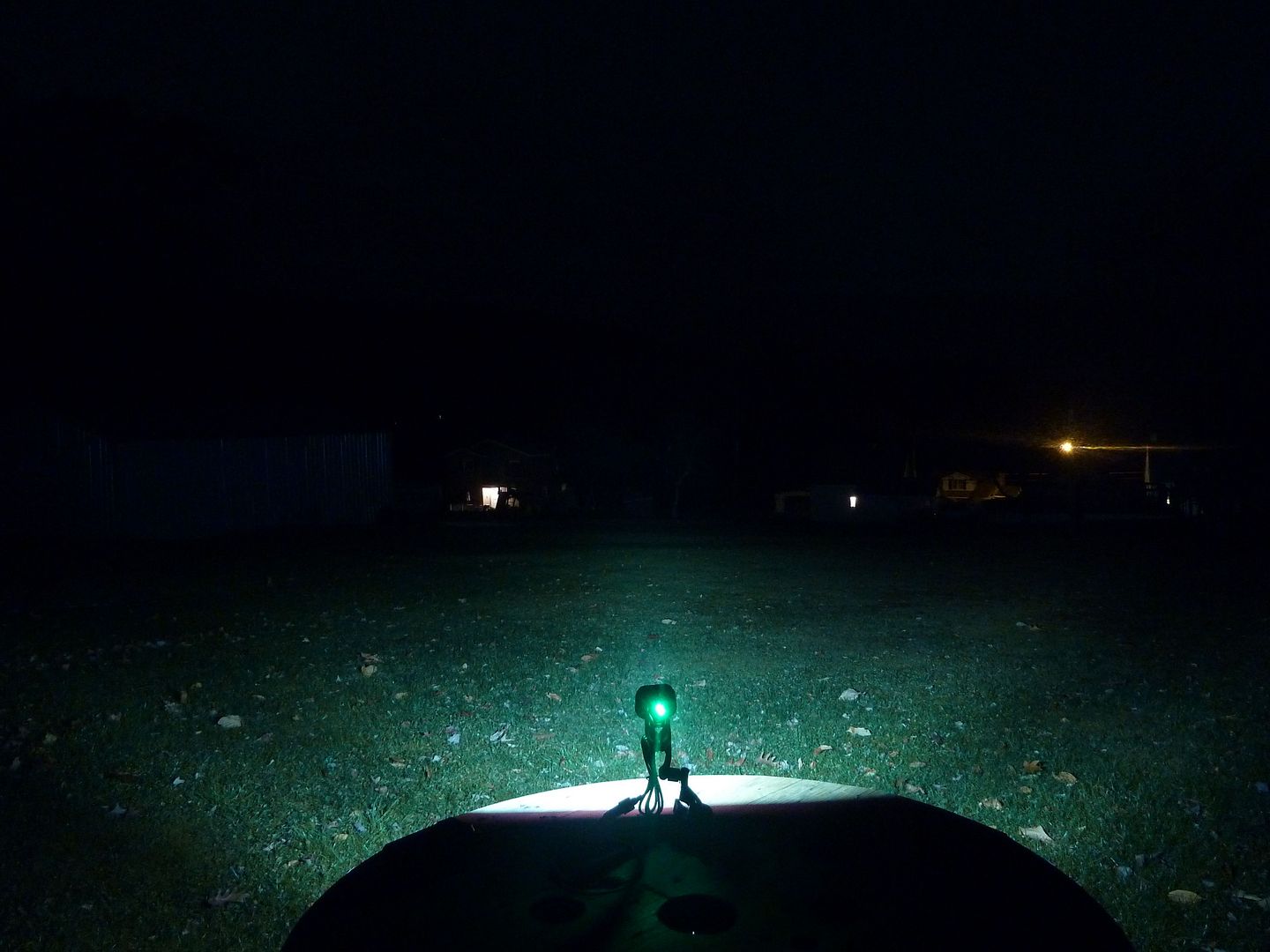
Modded Beamshots, distance to the two trees is approx. 185 feet (I aimed at the tree to the left). Approx. 275 feet to the house off to the left of the tree.:
Low:
Med:
High:
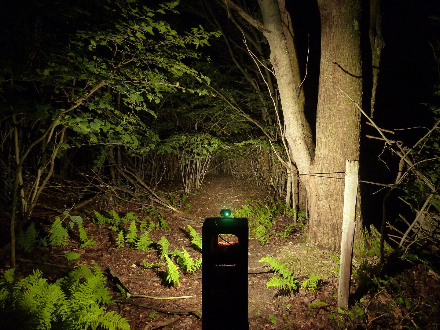
Wooded "simulated bike trail":
Low:
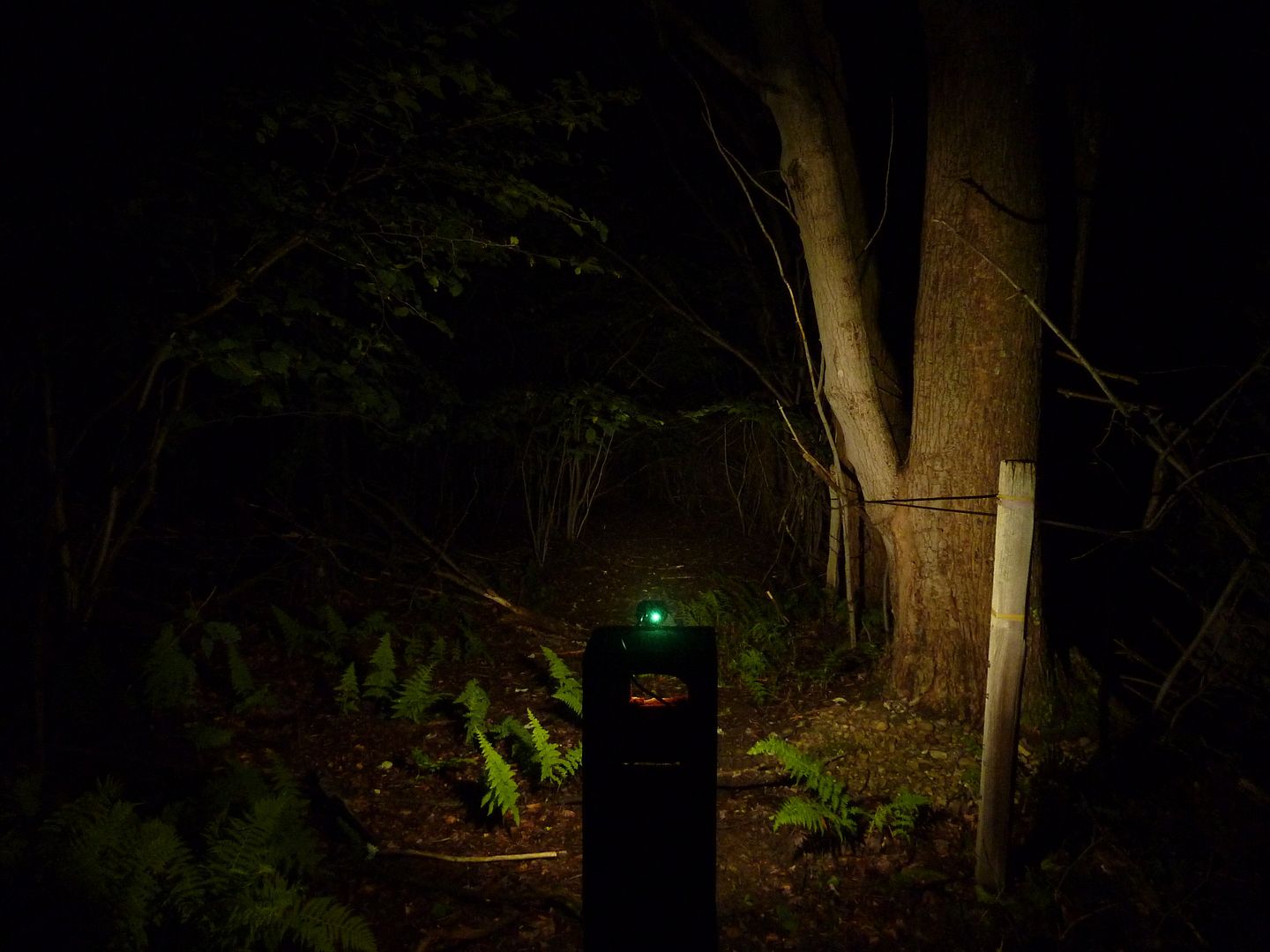
Med:
High:
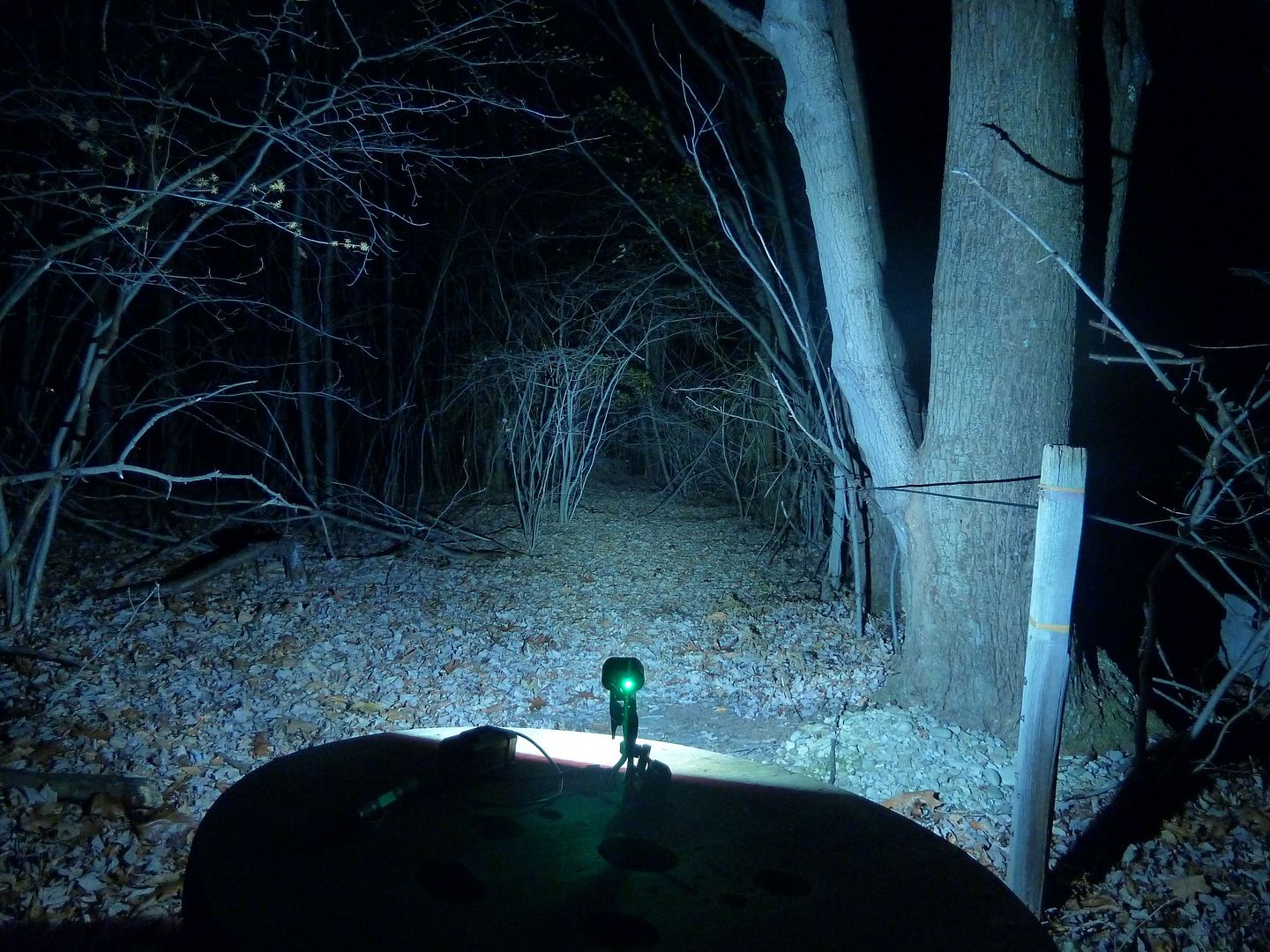
Mouseover's with original Un-modded Light (Mouse Out=Original, Mouse Over=Modded):
Yard:
Wooded:
-Garry
Really nice beam shots. Really dig the tint of those emitters. Really make the colors pop too. Thank you.
I think the beam shots belong in your bike light thread though because that is a great go to thread to see the beam shots from all your bike lights. Or, maybe make a copy the above post there.
Done. Yeah, the tint difference really does makes things "pop out" better. Even though the white balance was off, it still affects the appearance of everything not just the light output, so the detail you see with the wrong white balance is still the same detail you'd see if I had the white balance correct.
-Garry
Awesome mod. Seems like a lot of work though! Hard to understand transplanting the KD2 MCU was really the most effective solution given that you are unable to reprogram it. But the light seems to have turned out great.
I’m sure you are aware the 7135’s are spec’ed for max 6.0V (7V in absolute maximum ratings). I am curious how you have it connected?
Seems to me you could connect VDD to the midpoint between the emitters and that way the 7135’s never see the full battery voltage (it would see roughly half), but would still regulate the current. Another way to think of this is you wire it up like a normal 1S flashlight, but put an extra emitter and an extra battery cell in series with the battery supply (The extra battery cell would raise voltage, but the extra emitter would sink most of that). Current through both emitters would be the same, just as current through both battery cells would always be equal. Hope it makes sense. Can’t think of a downside but haven’t tried in practice.
Or perhaps you have it wired up to B+ and the parts are more robust than the datasheet indicates. Either way, I am curious how you have it wired up.
ImA can speak to the wiring. The KD2 MCU still retains the programability.
-Garry
Hi AceOne and welcome to the forum. The 7135's are connected as follows:
- Batt - (Ground) is connected to the large GND pin.
- LED - is connected to the OUT pin.
- PWM out from the MCU is connected to the VDD pin.
I may not be able to satisfactorily answer your question about why it works as I don't have any formal electronics training. I can tell you we have been using 7135's to drive 2S and, I think, even 3S LED's around here for some time. The key is to not have too much voltage differential between the voltage source and the Vf of the LED's.
The data sheet refers to the max voltages being in relation to Ground. So Ground and OUT seems to be OK based on that. OUT should be the differential between supplied voltage and the cumulative Vf of the emitters. So in a 2S light, it will be about double that of a 1S light. Given the high Vf of the XM-L2, this added voltage overhead is welcomed and is still well below the datasheet max. The PWM output from the MCU is limited to its Vcc (or is it called Vdd?) feed which is around 5 volts. For extra protection, I have really heat sinked the 7135's well. Another protection is that the FW/Driver set up steps down output way before the thermal protection built into the 7135's kicks in.
Hope that helps. Maybe a member with deeper electronics knowledge can give you a definitive answer.
The project was a lot more work than we planned as we had to change direction a few times. We really wanted to develop a nice Attiny13 solution for cyclists, but the chip just has too many limitations. Luckily the KD driver came around because it has pretty much all the functionality Garry wanted. The only bad point being that it drastically steps down for thermal protection.
EDIT: Been meaning to correct the above for some time. Not sure if I am right though. So if anyone knows better, please chime in.
Hey everyone,
since all the uniquefire modders are gathered here, I have a question on the long term stability of the driver when operated with 5 V (USB power bank, going with the idea of: 1 item, at least 2 purposes). The bank would be a 4x 18650 Panasonic NCR 3400mAh rated 2A at 5V.
Regarding ledomans review and measurments, both LEDs on: 1.2A at 8.4V (10W) and the 2.2A at 3.4V (7.5W), it should work quite fine (though the 3-LED indicator will always be blinking or with one LED on), but does it cause any harm to the (stock) buck driver to be constantly operated at 5V?
Last but not least: Kudos for the mod, you guys put a lot of effort into that one and it pays out! Well done!
I don't think there would be a problem operating at 5V input. It wouldn't be very efficient due to your power bank wasting energy to boost to 5V needlessly.
-Garry
Needles to say original HD-016 is powered by 8.4V (2S2P 18650 cells) and moded one is designed to be powered by 4.2V (if I'm not wrong). So stock HD-016 won't run from USB power bank unless you raise the voltage to at least 6.6V.
No, my modded one runs on 8.4v. If I remember correctly, the original driver did operate on 4.2v input - pretty sure of that.
-Garry
Nope, see my review https://budgetlightforum.com/t/-/29350 . So in either case USB power bank won't be usable unless you place step-up converter in between. Pretty useless.

Thanks for the posts, like I wrote, ledoman testet at 3.4V even. Also someone said, it worked fine down til 4V. I have tried it with an 5V USB bank and that worked as well, not that brigt, but that might have been because of the low output of that bank. So it works, but does it cause harm to the buck?
I think about getting a powerbank with an adjustable boost (5-13V), so i could rise the voltage up to 8.5V, but I guess that would be more inefficient than maybe 6V?
(I know, there are losses from 3.7V -> 5-8.5V -> 3…4V for the LEDs and I’ll have to figure out the optimum for the powerbank regarding runtime, but for the sake of simplicity in handling and less devices/multiple purposes, I want to do it that way.)
Ok. I didn't remember that it can run so low.
Still, you can't run it at full power (both leds on) if your bank can't provide enough current. When you lover the voltage you would need higher current gaining some more looses in the wires. Very likely you would need somewhere up to the 3A from the power bank.
Best to try it and see how it goes. Do a runtime test with a fan blowing over it. I'm no electronics expert, but I can't see how you'd damage a buck circuit from low voltage. I understand a typical buck circuit correctly, once you drop the voltage down to required level (or lower) the circuit has no reason to "buck" any voltage and just goes direct drive (letting your lower voltage level pass straight through). It still seems a waste using the power bank, but if that's what you want and it works out so be it.
-Garry
I agree with garrybunk's comments. Should not cause any damage to the buck driver (actually 2 of them in this light when stock. One per emitter.). It will just have lots of energy losses due to 2 convertions. First, the boosting of the cell voltage to 5V and then the bucking of the voltage back down to the Vf of the emitters.
It wouldn't work in the light modded in this thread because the emitters are in series and therefore need more than 5V to clear the LVP threshold and make a usable amount of light.
No, can’t do that. Have to ride til it dies! ![]()
Thanks for your thoughts about the electronics! I can try out now with good conscience.
Sure, there are losses due to the “senseless” up and down[1] conversion, thought about that a lot.
I bought a Qidian 3A 4x 18650 now, which has 2 USB 1A/2A and a jack out and is adjustable from 5 to 12V (about 15 bucks) and 4 Panasonic NCR18650b w/ 3400mAh (24 w/ shipping), so around 40 for the whole package and got that out of it:
- Bikelight battery pack with good capacity cells
- a charger for 18650 cells
- a USB power bank
So, the “losses” work for me, I guess, otherwise I would have had to order a 2S2P pack (around 40) and a quality charger with either a balancer (25 and up) or single cells (24), a single cell charger (10 and up) and a case for single cells (15, ok USB would be also included)). Or of course 40 for the pack and charge with the 8.4V/1A charger, not giving a … about the balancing.
Let’s see how that will work out, I can tell when the items arrive, if you want.
[1] pretty weird anyway, when you think of the 3.0V-4.2V of the cells and the 3…4V a LED requires?!?