^ Answer is yes. First sentence of OP has a link to where that was first done (Qlite and Nanjg have the same circuits, just higher "binned" 7135's in the Qlite).
yes indeed, hence the title of this thread referring to comfychair, this is just his mod with a smaller FET that fits easier, and cheaper driver.
Thanks for the replys.
Tried to find some one that used the QLITE in this thread but didn’t find. Excuse my noobness. Trying to learn the basics yet.
I’m in my second led flashlight mod. The first was an Convoy S2+, that was accidently dedomed when received 2 7135s to its driver. Now mounting a Uniquefire 1504 host, that will receive a dedomed XP-G2 S4 2b and a fet driver.
Cant wait the parts arrive to mount a fet hot rod thrower.
Can this driver be zener modded for 6V output?
Djozz
Could you confirm that with the qlite it is necessary to relocate the capacitor, mounting it before the diode and connecting it to gnd?
And with the Ak47, is it necessary to relocate the capacitor?
Yes, I did this for many times.
No, everything stays in place. Pull off the AMCs and add the Mosfet. That’s it…
Prisma, it isnt necessary to relocate the capacitor with the qlite and the Ak47?
For the zener mod, do everything you would do for wight's board, it is effectively the same driver. So I guees the cap should indeed be relocated, parallel to the zener diode.
This thread goes to my book :)
Does anyone else have this with this driver, which should not work different from wight's designs?:
Two cases of builds with this driver:
1) (small 16340 light with 219C) with the tail in place I get normal behaviour, the light works like a charm, but with the tail removed and while measuring current with my DMM the higher modes do not work, when tapped for the next mode it does that for a flash and then returns to lowest mode. Then I used a 0.01Ohm sense resistor for current measurement instead of the current going through the DMM and all the modes were back.
2) (Supfire F3 build with XP-E2) the stock tail worked fine (and was good enough for this 2A build btw), but when the tail was modded with a better switch and spring bypass, it would not stick in high mode. Low and medium worked but when tapped to high mode a quick flash and then return to medium.
I am not enough into electronics to understand what happens, perhaps if the minus wiring from battery to driver has too much capacity something happens??
In both cases when it doesn’t go to high, those are cases where you potentially may be drawing more current through the FET?
So maybe in those cases, because it’s drawing more current, it’s causing the voltage to sag momentarily which may be causing the mode switch?
Then, in the other cases, there’s more resistance, so less current draw, so no sag, so you can go to high mode.
A lot of maybes, but that’s a guess.
From memory some of the original HD2010's had a problem when testing not being able to measure current on some modes with the tailcap off.
I got one failure out of 10 of this driver. What could happen? I am really not sure cause it worked the night before I tested it. And next day did not. LED is OK.
Since I have nasty habit to hard solder driver to pill only way I could de solder my work is with heat gun, and of course it pops out after few minutes of heating, and so does other components on driver :)
I guess that I probably did bad wire soldering(22AWG)
I got one very important question for this driver(it is in picture):
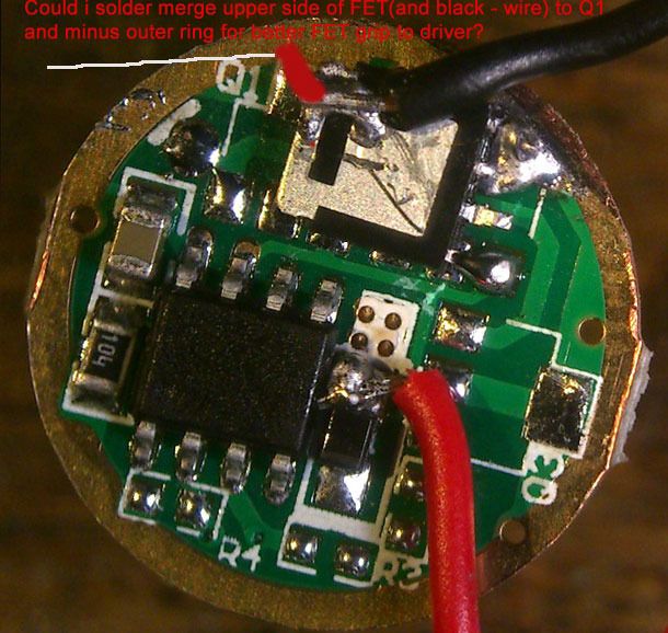
Question in picture: No, the tab / back of the FET and the black wire is “out” to the led. Ground ring of the driver is “in”. Solder them together and you bypass the driver entirely. Same as if you did straight direct drive with no driver.
If I understand the question well, yes the FET will stick better, but you do not have a driver anymore: batt+ was already directly connected to the led+, now you propose to connect batt- directly to led- : direct drive bypassing the FET. The FET is the switch between batt- and led-, the switching is directed by the MCU.
Fixing the FET is a good idea because it hangs on a few thin leads on the side and could be ripped of by the led- wire when assembling the pill, best is to use some epoxy or ArcticAluminaAdhesive or whatever.
Halo beat me to it :-)
Thanks on explanation guys. I am real dummy for some things. But I can always ask you guys. :)
I use artic alumina(don't know if you guys tried that in this build). But it should be done in right order.
I suggest solder FET black wire before gluing with AA. Why? If you firstly glue with AA and then try to do soldering wire to upper side of FET AA will unstick itself cause it is heat sensitive.
One more question... I bend FET legs for better direct contact to soldering points on Djozz picture. Do you guys do the same?
Yes, I do bend the legs with small pliers. The last few I did I bended the third leg sideways and included it in the big solder blob to the ground ring (in the OP picture it just hangs loose). That makes it just a little bit extra solid.
I have a couple of the ’generic nanjg with 8x7135 from fasttech.
Does this mod work with those?
Also I have some AOD510 MOSFETs. Can I use those fr this nod?
If so I guess I strip off all 8 7135s, but then what?
Thanks,
Jim
Edit: I did the mod, but not working… No light. Which MCU pin should go to which pin on the AOD510 MOSFET?
Just took a look at the AOD510 datasheet for you. AOD510 appears to be opposite of the PSMN3R0-30YLD. So the bottom left pin of the AOD510 goes to pwm.
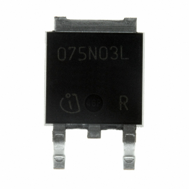
Instead of mounting it upside down like the PSMN3R0-30YLD you could place it right side up if you have some kapton tape to insulate the bottom of the AOD510 from exposed pads on the driver.
If you have no way to insulate the bottom you could place the AOD510 upside down but it would need to be oriented differently from the PSMN3R0-30YLD.