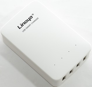
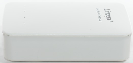
Linoya USB Smart Charger LY-001
Official specifications:
- Auto detect technology to keep your devices safe.
- Independent LED indicator light for power status, safety and convenient.
- Input: AC 100-240V
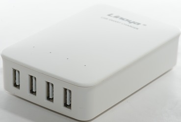
- Output: 5V /2.1A (2.4A Max. Totally 6A output)
- Model: Linoya A15
I got it from Gearbest sku:130434001
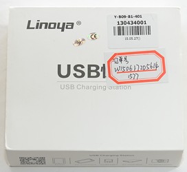
I got this charger in a cardboard box.
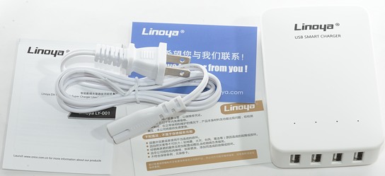
The box included the charger, a mains cable and instruction sheet.
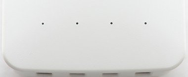
Behind the small holes are blue leds that shows when the channel is loaded.
Measurements
- Power consumption when unloaded 0.1 watt
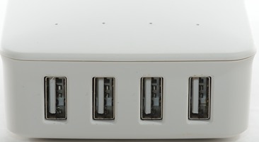
- USB port are auto detect with up to Apple 2.1A.
- All outputs are in parallel.
- The blue loaded leds turn on at 280mA and off at 250mA
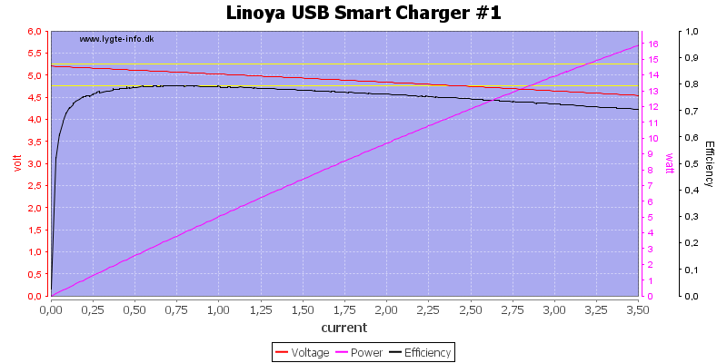
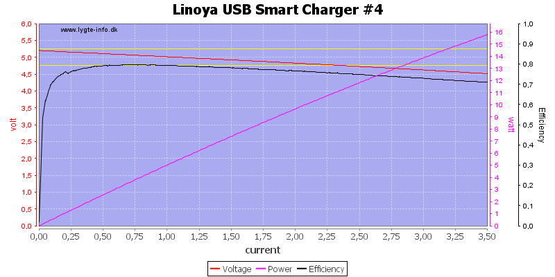
There is no individual overload protection on the channels, it does also look like there is some voltage drop with load, but it stays just within allowable limits.
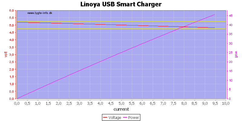
The overload protection is at 9.5A, this is rather high for a 6A charger.
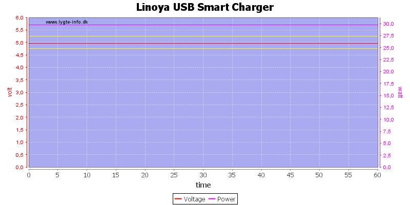
There is no problem running one hour with a 6A load.
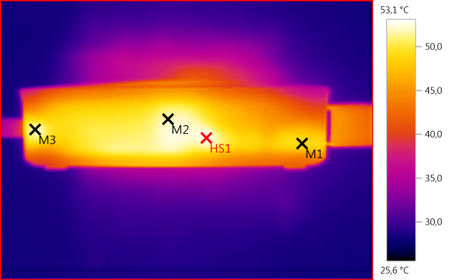
The temperature photos below are taken between 30 minutes and 60 minutes into the one hour test.
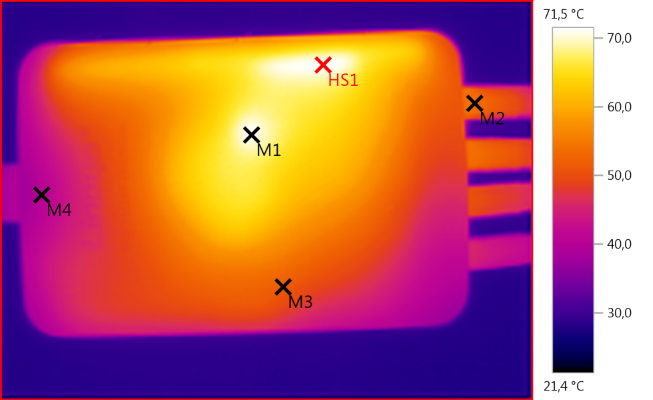
M1: 71,1°C, M2: 54,2°C, M3: 51,6°C, M4: 40,2°C, HS1: 71,5°C
HS1 is the two rectifier diodes and M1 is the transformer.
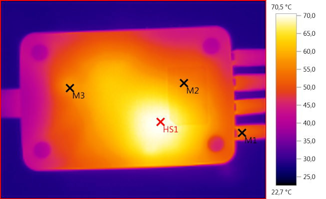
M1: 53,9°C, M2: 56,1°C, M3: 57,1°C, HS1: 70,5°C
HS1 looks like it is the circuit board track from the tranformer?
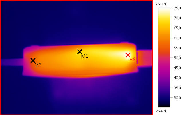
M1: 67,0°C, M2: 55,2°C, HS1: 75,0°C
M1: 49,1°C, M2: 51,9°C, M3: 51,5°C, HS1: 53,1°C
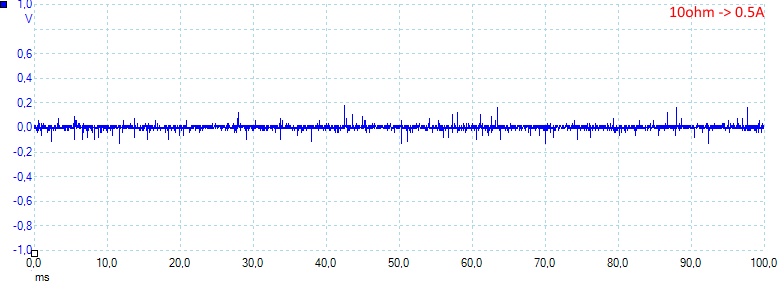
The rms noise is low at 15mV rms, the peak is much higher at 430mVpp
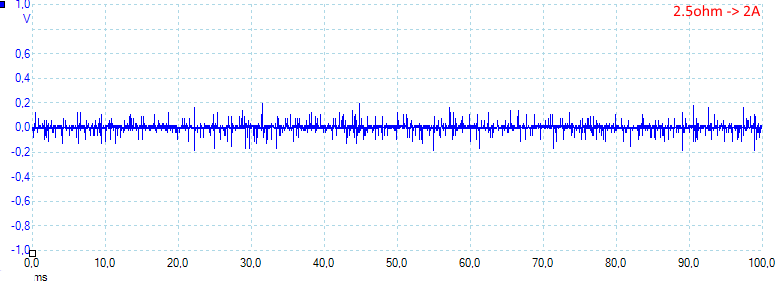
Increasing current to 2A: 24mV rms and 500mVpp
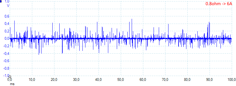
And at full current: 50mV rms and 1250mVpp
Tear down
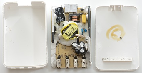
The box was to wide for my vice, instead I used a mallet to hit it a few time, then I could take the lid off.
On the lid there is some shields between the led indicators, to avoid light spilling between them (nice).
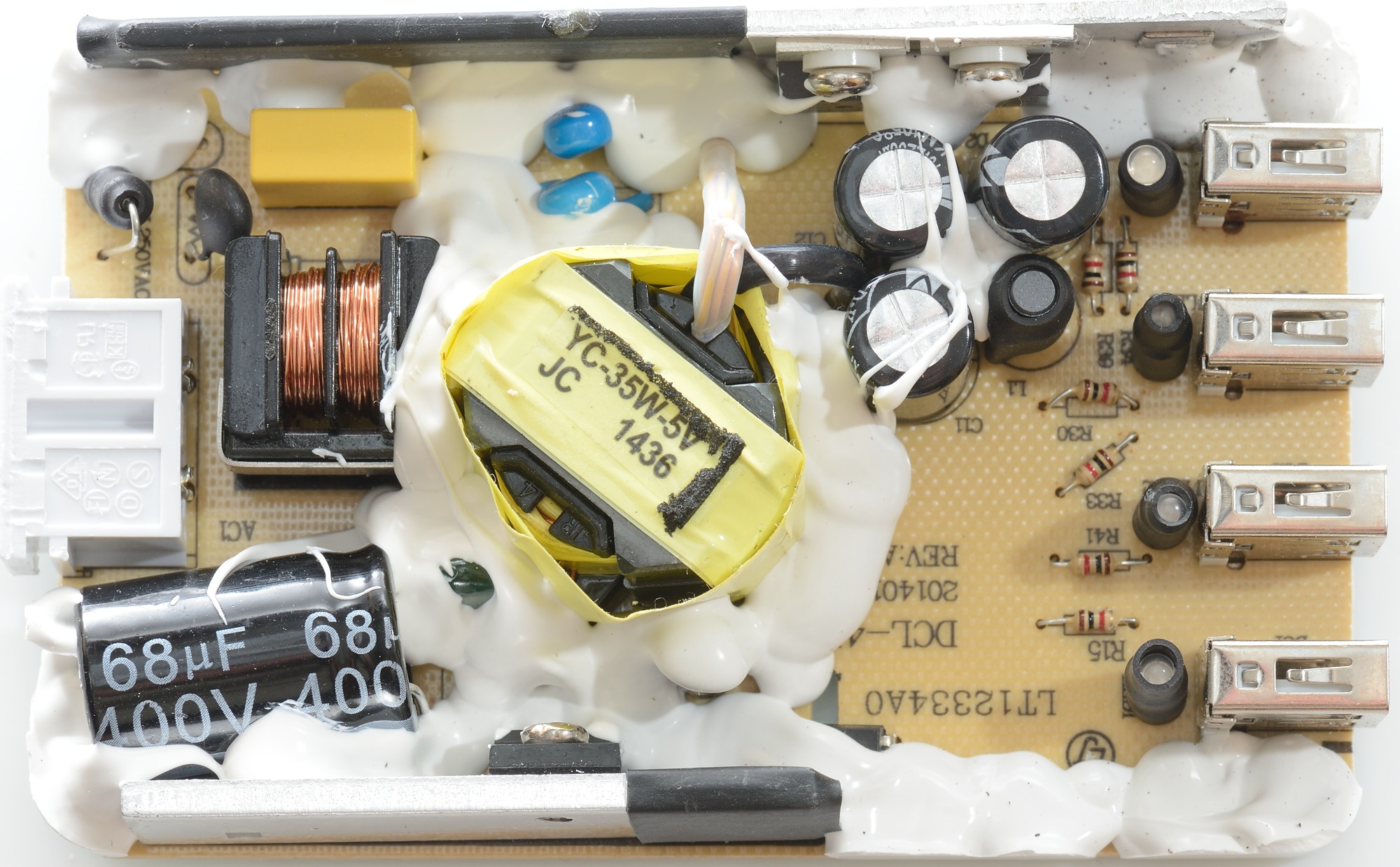
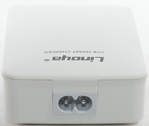
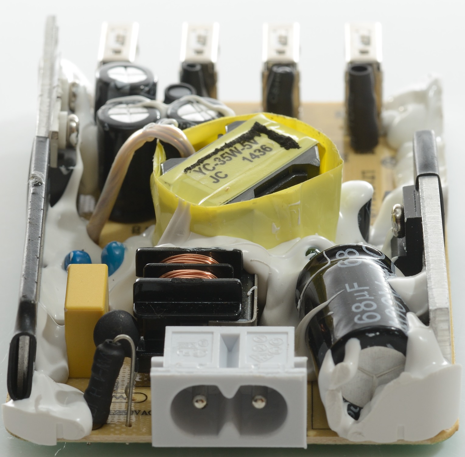
On the input there is a fuse and a resistor, there is also a common mode choke. Besides the transformer are two safety capacitors.
The mains switch transistor is on a heatsink and the two output rectifier diodes on the other heatsink. Hidden beneath the white stuff the corner of the opto feedback chip can be seen. Behind each usb connector is a led with black heatshrink on to avoid sideways light.
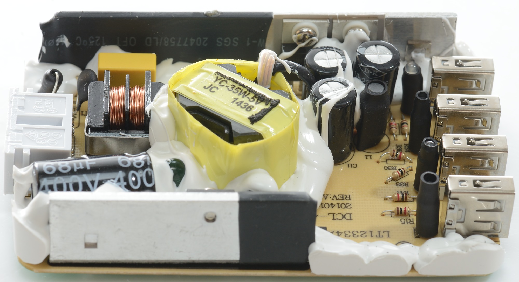
From this side here the heatsink for the main switcher transistor is blocking some of the view.
One interesting detail is that the two rectifier diodes is isolated from the heatsink. I wonder why because electrically there is no reason for it (Maybe it has something to do with noise).

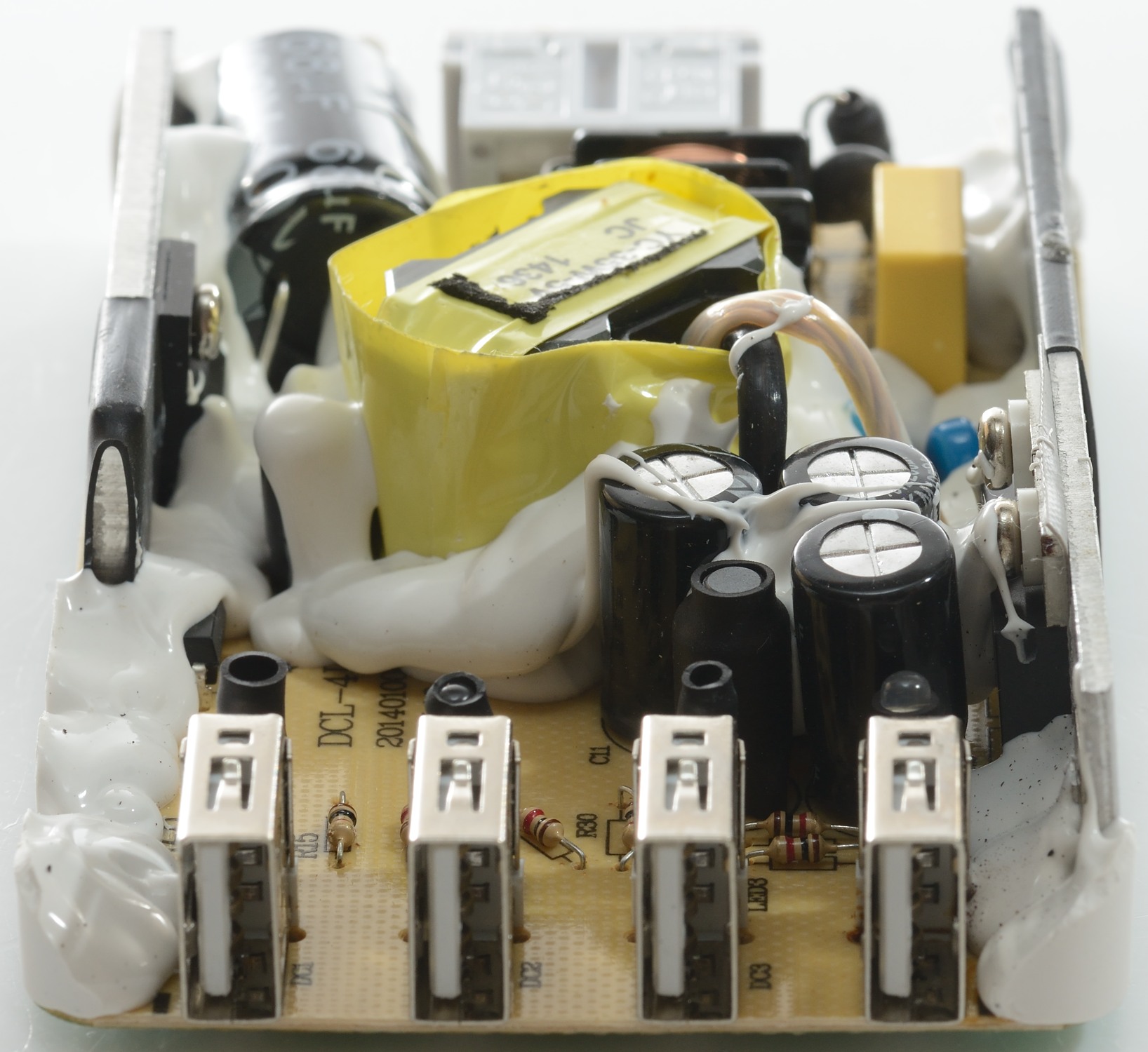
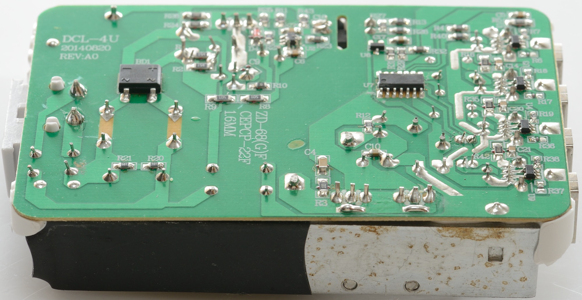
With the heatsink for the rectifier diodes taking up the full length of the circuit board, there is not much to see here.
The secondary connections from the transformer can be seen.
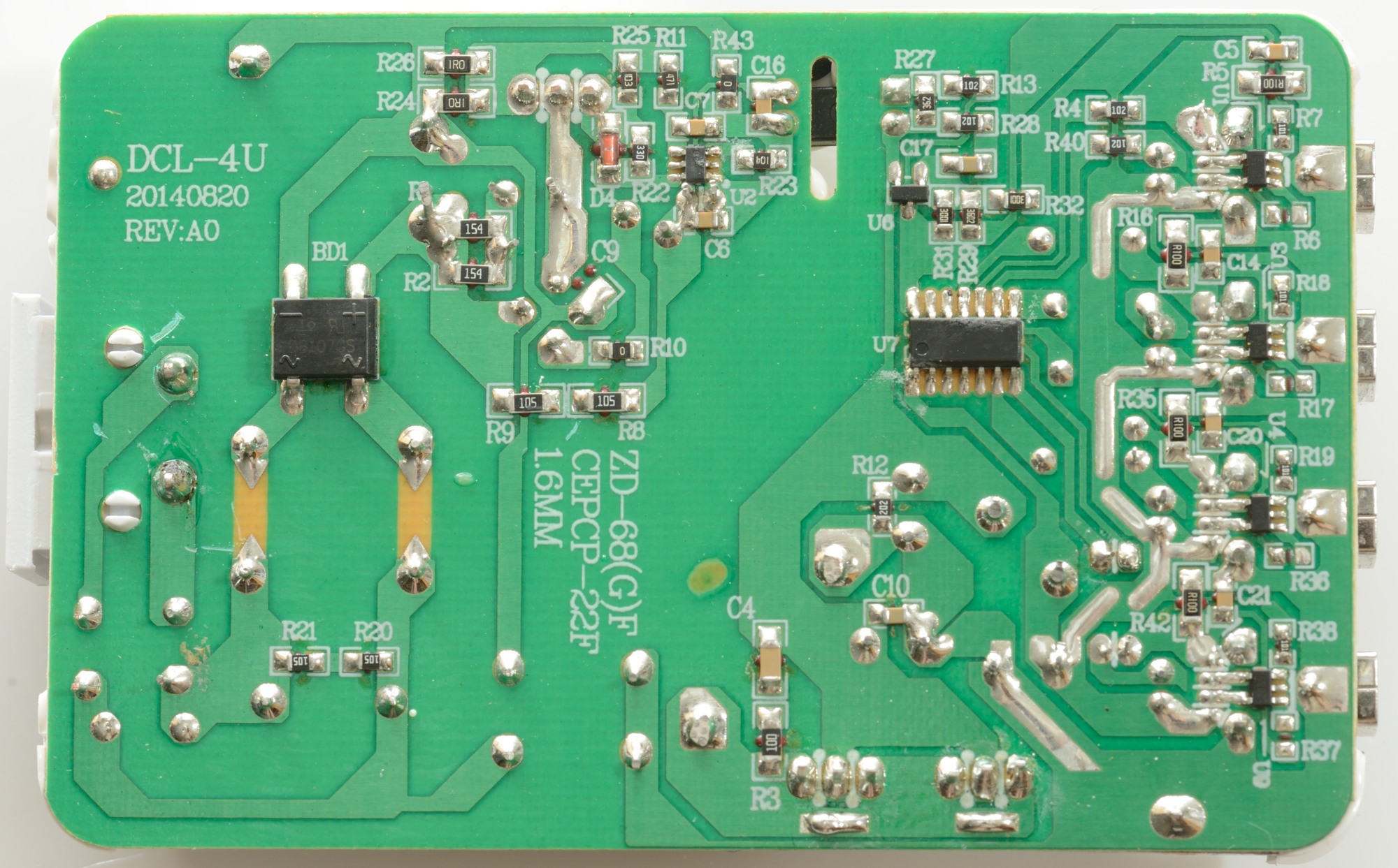
The input rectifier bridge (BD1) is here and the mains switcher controller (U2).
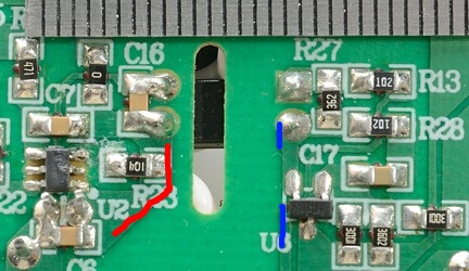
On the low volt side there is the chip to control the the leds (U7) and the chip to control the optical feedback (U6). Below each usb connector is the automatic mode chip (U1, U3, U4, U9). It looks like there is a 0.1ohm resistor (R100) in series with each output for the led indicators to work.
Look at the circuit board track around C10, it looks a bit special with narrow tracks where the capacitors (on the other side of the board) are connected. I wonder if this is the reason for the hot spot on the IR photos.
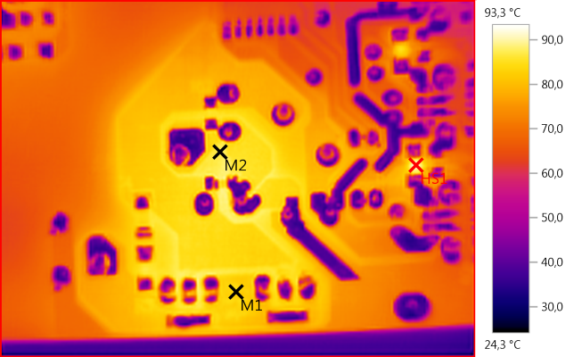
M1: 83,7°C, M2: 87,1°C, HS1: 93,3°C
I got curious enough to check and yes it looks like it is the track. I did check the other side and neither the capacitors or the transformer is hot enough to do this.
One little detail that also shows up here is the 0.1ohm resistors, the do get fairly warm.
There is a very good safety distance on this power supply.
Testing with 2500 volt and 5000 volt between mains and low volt side, did not show any safety problems.
Conclusion
Generally this adapter works fine but I would have like considerable less noise at full current and individual overload protection on the channels.
The indicator lamps are an interesting idea, that makes it easy to see when a device is about finished with charging, but there is a small downside with the voltage drop.
Notes
The usb power supply was supplied by gearbest for a review.
Index of all tested USB power supplies/chargers
Read more about how I test USB power supplies/charger