I don’t think any of them do that by default, but it should be a relatively easy change to write.
I think I should be able to figure it out. If it works out I’ll let you know. Thanks again
ok. I am completely lost. I have read every post on this thread and multiple other threads like this one and this one and this one. I am using a Mac, which makes it worse because most of the info is about using AVRDude. I downloaded Crosspack-AVR. I am unsure if there is anything else I need. Is there a step by step guide on how to do this programming? I read the info at Ladyada.net and I still don’t understand it at all. I saw a thread that had screenshots, but none of the pictures were viewable. I have built 2 of the USB devices to flash the MCU’s but I don’t even know how to properly test them. I have 20 Nanjg 101-AK-A1 that I want to change the firmware on and I have 20 separate Attiny13a’s that I’ve ordered just sitting there. Where is the guide for morons for this? I just want to do simple programs, but it seems I may have just wasted money. I don’t usually let stuff get to me, but I just can’t wrap my brain around this stuff.
I haven’t used a Mac, but I took a look at the ladyada tutorial and AvrMacPack (now CrossPack), and I think I might be able to explain it.
Basically, CrossPack (after being installed) gives you a setup very similar to what I’m using in Linux. This means you should have avr-gcc and avrdude and the other necessary tools, but you will need to use them all from a command line. Are you at all familiar with using a terminal?
You’ll also need a decent text editor. I hear TextMate, SublimeText, and Kod are good. I’m using Vim, and have also seriously used Emacs, but I wouldn’t suggest either one to start with.
You might also want to install bzr, so you can grab and update the sources automatically, make your own branches, etc.
If I understand correctly, after you have all the parts you need, the process would be something like this (bold means it happens in a terminal):
- Download and unzip a copy of the firmware repository. Or just bzr branch lp:flashlight-firmware if you have bzr.
- cd flashlight-firmware to change directory into the code tree.
- Pick a project and cd into it, like cd ToyKeeper/blf-a6 . You can probably tab-complete most of the command line (type a couple letters then hit Tab and it’ll finish the rest if it’s unique).
- Edit the code in a text editor.
- Compile the code. …/…/bin/build.sh blf-a6
- Flash the code to an attiny: Type in ./flash-noinit.sh blf-a6.hex but don’t press Enter. Connect your clip to the attiny, plug it all in to USB, then hit Enter.
The build process and flashing script may vary from project to project.
I’d also recommend getting familiar with other common command line programs, but that’s mostly optional. I think all you really need is ‘cd’ and some scripts in the code repo and perhaps ‘make’ for projects which have a Makefile. Might be nice to use ‘ls’ or ‘ls -al’ too (list contents of the current directory, perhaps [a]ll files in [l]ong format), to avoid the need to switch to a file-browser window all the time.
hi again,
today I’m trying to flash the blf-a6.hex -file, but I’m getting an error. I’m trying it with a bare MCU, wanted to do that before soldering it to the driver board, don’t know if that makes a difference.
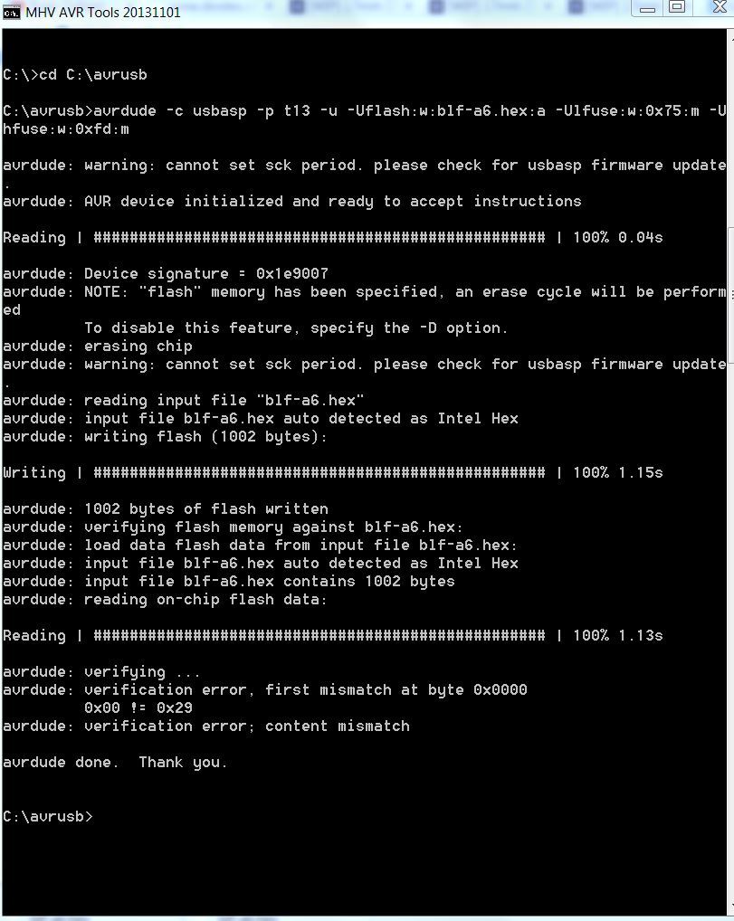
I usually see the verification errors only if there’s a pin not connected during flashing. Six pins are required:
- 1 RST
- 4 GND
- 5 MOSI
- 6 MISO
- 7 SCK
- 8 VCC (don’t forget VCC, even though it’s not in bold in the table below)

BTW, it can still be flashed after soldering to the PCB… but only if you don’t have any extra pins grounded or stars soldered. I reflash MCUs on drivers all the time.
Yeah I agree with TK, usually I only get that error if I bump it while flashing
Thanks Toykeeper (EDIT) and pilotdog,
the connection didn’t seem to be the issue. I checked with following command from Hoop’s guide:
avrdude -p t13 -c usbasp -n
I have tried to flash different firmwares to these new bare MCUs I ordered, everytime I got the same error. When I tried to flash these firmwares to MCUs that were sitting on a 105C already, it worked.
Now I changed the jumper on the USBasp to the 5V setting and guess what… it worked with the bare MCUs. I have no clue why that is, but I’m glad it worked.
I’ll let you know how I like the firmware when I finally manage to get a driver soldered together and have it installed in a light.
Ah, I forgot about the 3.3V / 5V jumper. Mine came configured for 5V and it has never been an issue.
BTW, the avrdude connection check will still pass even with VCC not connected. I flashed drivers for several weeks (with verify errors each time) before I figured out there was a physical connection issue on my VCC, but after fixing that things have been much better.
Not sure if this is the right place but I know TK had seen problems with the OTF cap timing when using a 22K resistor. Would there be the same problem, or worse, with a 36K resistor? I'm seeing awful results - when cold, quick clicks don't change modes, then after a few clicks it starts working, but as a long click (in the BLF A6 driver, moon to hidden turbo, etc.), then after a while the quick clicks work the way they should, but long clicks seem impossibly long... Ugh it's pretty useless in this setup - guess could be a bad part, but again, first time I'm trying a zener mod with the 36K resistor on a 22mm wight FET+1 board (https://budgetlightforum.com/t/-/31559).
Hi
I would like to change the turbo on blf-a6 firmware to a smaller value.Is this possible? I changed “#define MODESNx2 0,0,79,255” to 0,0,79,175 ,the max output was reduced but the turbo timer didn’t work anymore .Should I also change the “line 117 #define TURBO 255 // Convenience code for turbo mode”?
Yes, it changes the OTC values significantly. You’ll need to recalibrate the OTC values and voltage values completely. The tools for this are under ToyKeeper/battcheck/offtime-cap.hex and battcheck.hex.
Voltage is relatively straightforward; connect it to a power source with the voltage you want to measure, read the blinks, put that value into your target firmware. Repeat for each voltage level you need to measure.
Offtime is a bit harder, unless you have a robot to press connect/disconnect power with very precise timing. Basically, connect power, disconnect it, wait for the time you want to measure, connect power again. Repeat a bunch of times to get an average, and use that.
If you keep getting 255, it means the time is out of the MCU’s measurement range (too short), or a 0 means it’s too long. The problem I get is that it stays at 255 for a while before the OTC voltage drops into the usable range (especially when the light is cold).
Ideally, you want both voltage and OTC values to be near the middle of the measurement range for the best accuracy and consistency. The values should ideally center around 128 or so, though really anything between 64 and 192 is good. Probably anything between 32 and 224, really. Outside of that though, it’s getting into the range where it’s hard to measure reliably. The only way I know to adjust this is by choosing different resistors.
But I don't see any consistency, so don't see how calibration could work. Right now when it's cold, long press's are the only thing that work. After playing with the modes a few time, short press's are all that work. It seems temperature related, so how could I calibrate to anything?
Yes, you should also set TURBO to 175 if you want step-down to work. ![]()
Also, if you want the modes to remain evenly-spaced, I suggest running the bin/level_calc.py tool to calculate a whole new set of PWM levels. If you don’t use 255 though, you may need to edit level_calc.py to either set the value there or uncomment the line which asks you for that. Here’s what it does after I uncomment that line and re-run it with a max of PWM=175 for a 960-lm turbo:
> ./bin/level_calc.py 4 1 10 175 960 y 20 10 140
1: visually 2.15 (10.00 lm): 0.00/255, 20.00/255
2: visually 4.72 (105.46 lm): 0.00/255, 192.56/255
3: visually 7.29 (388.17 lm): 64.68/255, 255.00/255
4: visually 9.86 (960.00 lm): 175.00/255, 0.00/255
PWM1/FET  values: 0,0,65,175
PWM2/7135 values: 20,193,255,0
I got 960 by estimating an actual maximum of 1400 lm, then multiplying that by 175/255.
If turbo isn’t 255 you could also try making turbo a little more efficient by putting some of the load on the 7135 chip. On a XP-L or XM-L2 it’ll generally get about 140 lm on the 7135 alone or 1400 lm on the FET alone… so subtract 140 lm from the FET value and set the 7135 at full. In this case, it would mean the brightest mode is 150 on the FET and 255 on the 7135. But that’s totally optional; it’ll make turbo more efficient, make the PWM harder to see, and make its tint slightly warmer.
Temperature is probably an issue, but the two calibration firmwares can at least quantify the issue for you. If it gives you crazy numbers, the hardware isn’t going to work. If it gives you okay numbers, you can be sure the hardware is okay and everything else is a firmware problem.
I'm not sure what good quantifying the problem would be? It's still a problem. Do you know if anyone has ever used OTC with a zener mod with the higher resistor values recommended? I haven't seen much in ways of posted details. Dale mentioned something about adding a cap or resistor on his zener, but with no explanation - never heard of that, or seen anything posted about it - dunno, if it was to address this issue or not.
For now I'll try a NOINIT firmware version, though it doesn't have the FET/7135 support in there now - not enough time to merge it in myself.
I just disabled the Offtim3 presses and it works fine as a normal offtime switching.
Doesn't this mean you lose hidden modes? Are you using value of 190? Are you using a higher R1 resistor, like 36K?
Yes, you lose hidden modes, but tbh I didn’t really want them anyways. I prefer very simple UI’s (all of my lights are either 3 or 4.mode), but I still love Blf-A6 for access to 2 mode groups and memory soft-toggle.
I think i used a 38k in my last one and the value was around 180-190
Quantifying can tell you if it’s a little off or if it’s totally out of the ballpark. Besides, if you want LVP to work you’ll need to calibrate the voltage anyway.
I think RMM has made zener+OTC lights, but I don’t know the details. I’ve mostly avoided serial-config lights and higher-voltage emitters.
BTW, if you can’t get the 3-level offtime to work, you could still use it without blinkies, or you could move the blinkies to the second mode group, or whatever. I could even make the basics work with mem decay instead of the OTC if needed, but note that the OTC interferes with mem-decay timing so it’s a good idea to remove it or ground it or make sure it never gets charged.