Can you try it with a half-full or weaker battery? The voltage may be boosting too high for the MCU which causes it to glitch. I've seen this happen on really heavy loads with full high-drain cells on some drivers.
That is definitely weird. I wonder if it uses on-time (exclusively) to determine whether to enter programming mode, and off-time (exclusively) for changing modes. That way, an issue with the OTC draining too fast could result in the symptoms described.
Maybe the OTC got shorted so it can’t hold a charge?
OK, so a weaker cell doesn’t appear to make a difference. But now it won’t go into programming mode. Grrrrr. I know for sure that the lead wires are not shorting out, and the jumpers are on for parallel operation. The driver isn’t bottoming out in the pill, and it was the best reflow job I’ve done yet.
D o e s n ’ t m a k e s e n s e.
I try to always test in phases, sounds like you did the same thing, I'm just not clear - what was the last configuration that the driver worked properly in switching modes? I know you said soldered the driver in and it worked, but was the LED's all soldered in place? Is it a removable pill assembly? I pretty much always test with a real cell on the pill assembly, then after installing the pill, test with a cell again. The PS is great for doing a first trial at low power, but after that, I'll still test with a cell.
I find it really helpful to have a couple alligator clips which lead to wire with exposed ends, so I can clip one to the ground ring and one to the spring and then hold the wires onto a battery for testing. Or hold them onto the battery and tap the clip against the body to test after putting the pill in. Or a variety of other methods, testing at each step like Tom E suggested. It really helps with determining what failed.
I’ve had some which fail after putting the reflector in, which is fixed by putting kapton tape on the back of the reflector. Yesterday I had one where the front half of the light worked but it failed after attaching the back. It turns out that one was a bad switch.
Last working configuration was with LED’s soldered to MCPCB, MCPCB soldered directly to the pill, lead wires soldered to MCPCB and driver, driver soldered into pill. But I didn’t test “extensively” after soldering the driver in place before assembling, so if it’s something that takes a bit of time to become damaged it’s possible it just hadn’t happened yet, but could have if I tested longer before assembly. My gut is telling me that something bad is happening in assembly when the carclo optic seats. The only reason I’m not more confident is that all 3 LED’s light and appear equally bright.
Could check the LED wires for signs of cuts at the openings - it's happened to me before. The silicone wires will get cuts thru the insulation pretty easy, and results can be intermittent, frustrating... Dunno - that might be a long shot. Hard to imagine scenarios where the Carlco lens might be causing a short. With the MCPCB soldered down, no chance of twisting. Could be some short relating to something on the edge, against the host body, again, long shot. Weird it happened with two drivers...
I actually trimmed them back when I reassembled with the second driver to make sure this wasn’t happening. When my son goes down for a nap this afternoon I think I’m going to replace all 3 LED’s and see if the second driver starts working(assuming it checks out ok after I remove it from the pill, if not I’ll try another one). If not I’ll be starting completely over with a new MCPCB, LED’s, wires, and driver all at the same time.
Not going to make anything on this build. Oh well, the risk of living on the edge.
That really is frustrating. I feel your pain. I've been doing this for a while and I still get crap like this that I can't figure out. I think that it happens to all of us, even if we don't post about it all the time!
Is the off time capacitor touching anything?
Is the switch too noisy?
I think I'll be able to use one of the old BLF DD two sided driver boards for this project, to keep things fairly neat.
This is what I have in mind;
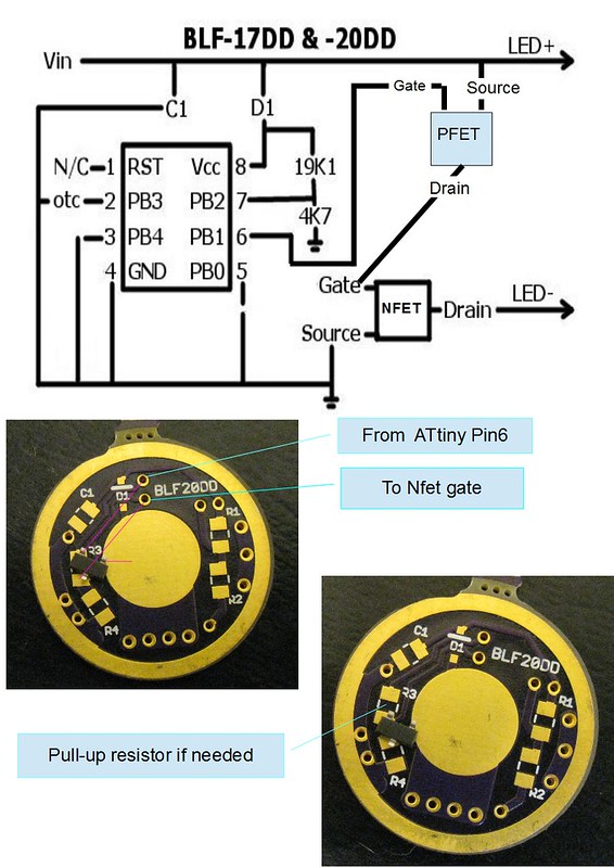
Note, the PFet is upside down, to get the legs where I want them.
If I were to require a pull up resistor, what value would be a good starting point?
You have a short in that diagram. It will have the sort of problem that makes the bad smell. :evil:
Hmmm - Richard seems to think that circuit would work (Look back to post#268 in this thread where we were talking about it).
The XHP's from MTN should arrive any day now, & I'm at the stage where I need to put a driver together to get things happening with the build.
Can you elaborate on why the magic smoke will escape? :)
Sorry. I wasn’t noticing C1.
Richard,
I've built the driver today, but I'm having trouble getting modes to work. It's stuck on full output.
I have tried pull-up resistors from 10k - 220k between the Source & Gate of the P Fet.
I also tried a 100 ohm pull down resistor on the big N Fet, between Gate & Ground.
I'm wondering if I have something wrong in the firmware;
When you say to invert the PWM values, do you just mean that Highest mode is "0" & Lowest (off) is "255" , or is there something else I need to change in the firmware as well?
Cheers.
If I understand correctly, PWM=0 would be the highest mode, and PWM=255 would be off. Anything between would be, well, between.
If it’s stuck on maximum, is there a short somewhere?
Or perhaps is it always resetting to the first mode, unable to sense how long it was off? You might want to try an on-time based firmware to rule out that possibility.
I removed the P Fet (taking the driver back to a regular Zener-modded driver)to check operation, & it tested OK with mode levels(albeit reversed, now).
...But on further reading, I think what Richard is saying, is that the actual signal from the Attiny needs to be inverted.
I came across this info, but I'm not sure how/where to add it into the firmware.
Specifically, the following is what I believe needs to be changed;
---------------------
COM – Compare Output Mode
These bits are used to set the Output mode in various Wave form generation mode. For Fast PWM mode these can be used to achieve following output modes.
COM01
|
COM00
|
Output Mode
|
0
|
0
|
Normal Port Operation (OC0 disconnected)
|
1
|
0
|
RESERVED
|
0
|
1
|
Non Inverted PWM
|
1
|
1
|
Inverted PWM
|
-----------------
So I need to put a command in there to set COM01 & COM00 to 1,1.
...I think... :~
- edit -
The info I linked above appears to relate to the ATmega16 or ATmega32, but I basically need to do the equivalent to the 13a.
I would maybe take the attiny off and try some manual switching first with it powered up to make sure that it will indeed work. If you need a pullup resistor 30K-100K should work fine.
From the attiny13a datasheet:
In fast PWM mode, the compare unit allows generation of PWM waveforms on the OC0x pins. Setting the COM0x[1:0] bits to two will produce a non-inverted PWM and an inverted PWM out- put can be generated by setting the COM0x[1:0] to three
What did you do exactly? Did you use the driver like in the schematic with two cells in series(8V)? I am asking because I don’t see a voltage reducing element like the Zener diode in the schematics and so you would grill the tiny.
——
Jist some info you maybe have missed:
standard firmware enables a pull down resistor for the output so that always if there is no high output the FETgate will be pulled down to GND to stop current from flowing.
The pfet will be standardized let current flow with the standard firmware in 0 mode because it gets connected to GND with the internal resistor.
On a mode 255 it should be pull the pgate to VcC so it should stop driving the nfet gate high but then you need a pulldown(additional hardware resistor(that what the the software pulldown is on standard drivers))
I'll give that a shot tonight.
I'm in the deep end here, & my Google floaties are barely keeping me above water...
Assuming the manual switching works, what would be the code to change the wave form?
Something along the lines of; "#define COM0x[1:1]" ?
------------
It's a Zener modded driver.
Sorry, the schematic was just for me to get my head around how the P Fet fit into the circuit.
So in addition to inverting the PWM signal, I need to put a pulldown on the NFet gate?