I’ve heard the crelant lens weren’t that great. They may be the same. Who knows.
Just as an addition to the numbers, yesterday I build up a 1504 host for another member: tail switch spring bypassed+brass top soldered to spring, driver spring bypassed, AK47driver with all 7135 chips removed, replaced by FET, short 18AWG ledwires, dedomed XP-G2 S2 1D on 16mm Noctigon soldered to pill, pill blackened with matt heat resistant paint.
Current just under 4A, throw measured at 5meter distance, with full Keeppower 4200mAh, 30 seconds after switch-on: 428kcd.
Nice Djozz

400k+ at Under 4amps? Wow
Very nice :) Could that FET mod be done with Nanjg 101-AK-A1 driver?
Edit:
N10Sivern would you be so kind and check your PM list. Thanks.
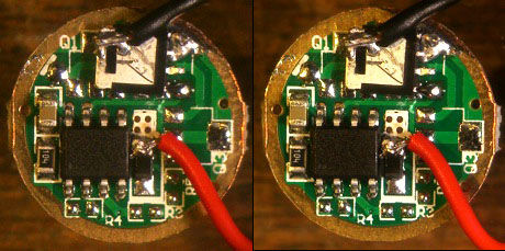
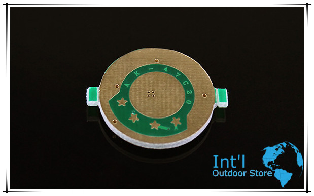
Sure, it worked for the 105c (https://budgetlightforum.com/t/-/25164) and the ak47 (https://budgetlightforum.com/t/-/32231), so why not for the 101ak? But convenient about the ak47 is that in the middle of the board it has 4 exposed via's from the batt+ ; scrape off the solder mask over the via's, fill them up with solder and you have a beautiful direct connection from battery+ to the led+ wire. The batt+ via's from the 105c and the 101ak are under the MCU, so all current necessarily follows a piece of thin circuit trace before you can connect the led+ wire. Should not make a great difference, but every tiny resistance counts with the XP-G2.
This FET is made by DJOZZ
Looks more convenient than stacking chips.
I have silly problem discovering what is vias?
Is that 4 holes near +wire that leads to + board on other side.
On your first version they don't seems solder filled. How do you fill them? Is it hard to squeeze solder through them on other side of driver...Maybe it would be good with solder paste? Or to messy...
Could it be good idea to drill through 4 tiny holes and make 1 larger one and to merge that with + wire contact and to bridge to other spring side + contact?
Edit: I think this is safer than Cajampa style DD mod cause it has reverse polarity protection, low voltage protection + mods should be working...
Djozz how low and medium mode looks to your eyes with this :) ?
Yes, the via's are the holes connecting the two sides of the board, on my picture the solder mask is still present and holes are not filled yet. I just heat up with the solder iron and just add a generous amount of rosin core solder wire and the holes will fill up. If not all holes are full, you can have another go from the battery side of the board.
Drilling a hole is a sure way to get it done as well, but filling up those via's (or even not filling them up probably) is way sufficient.
Thanks :),
Does this mod have any influence on mode changing?(mode memory is still present?) and how it looks on lower modes like low and medium?
The lower modes look normal, and so does memory. I never checked the low voltage protection and reverse polarity protection, but I see no way how they should be affected by this mod (the board lay-out is effectively the same as Wight's board, which is directly derived from these NANJG boards).
A tip: glue the FET down, because being upside down it is only soldered on one side and the led-minus wire attached on the top could rip it off while fiddling to get the driver/pill/ledboard attached. I never glued it but the FET did tilt during this last build with the thick led wires.
Tip2 solder two legs from the Attiny together (or connect one of the stars to ground) to get rid of the blinkies.
Thank you very much Sir! You are one extraordinary man (you would not believe how much you helped me past two years...)
10xAK47 driver ordered from FT (although I have single mode AK 101/105's like drivers that are bit different from original nanjgs).
For glue advice I think I will use AA for FET and pot whole driver with Fujik.
Will try to run protected generic cells like samsung 2600 on this cause I don't need currents higher than 3A.
Your thread here is very educative.
Djozz,
I am just curious about one thing here... Did you left stock omten switch or you swapped it to another one?
I left in the stock switch, it did not say Omten but looked decent enough, was that a wrong assumption?
These type of FET drivers hardly produce heat, they can float in air if you want.
And I still find it surprising that what I test or make up in the middle of a city in a country that never really gets dark, appears to be actually useful for folks who properly make use of flashlights :-)
Plenty of guys said that original switch sucks.
In your thread MRsDNF did review of 1504 switch in post 51.
I don't see any problem with it although I do re solder contacts to make sure it sticks good.
In fact I got one batch of omten switches from IO store that looked absolutely the same as UF's but they did not have any omten markings on front or rear.
Maybe you would have even better performance with genuine omten?
I replace my switches with Omten or Kan’s. I’ve burned up a few of the stock switches.
Hmm, already put the light in the mail. But Nicolaas lives in Amsterdam, when I see him sometime I will replace the switch all the same.
The ones I burned up were running at 5A. They would handle it for a little while but ultimately would fail. There were some that didn’t fail and only 2-3 that did fail, but to err on the side of caution I just replaced them.
Guys,
Where did you bought your genuine omten or kan switches? Can you link some to people. I saw on FT https://www.fasttech.com/products/1135000 but I am affraid to risk. TomE said this:
I don't know what to do since I did ordered from IOS and they came without any markings. Never did complaint to IO about that. And switches are working fine. But this kind of threads, and switch reviews makes you think what have you actually bought...
Or maybe some of you guys tried to fit forward clicky to UF brothers?
So these switches from IOS came unmarked?