Interesting info! I'm still waiting for my boards and some parts as well. Thanks for posting! I'll go for blue and maybe I will green too.
Really any color is fine for low output levels from what I’m seeing. It’s when you want it bright enough to see in a well lit room where the differences come into play in a big way.
Blue and green seem to be the most efficient, and honestly I’m not shocked I guess. In addition to the fact that I think the Vf is at play, I don’t see many high output red LED’s in flashlights either. I think the material that filters the light into red from the LED has a big effect on output. This is why high CRI LED’s are generally lower in output than their low CRI equivalents. Blue has the advantage of needing less filtering and we perceive it to be brighter than red for the same lux value. Green is the same way, less filtering than red and higher perceived brightness for the same lux.
Add all these little things together and you have a red LED that is hard to get big brightness from when you compare it to green or blue.
Only white leds use a phosphor layer (and odd leds like pink). Colored leds produce their color directly, no phosphor layer or filtering.
Green is perceived as as brighter to our eyes.
That’s good to know. I guess half my theory wasn’t worth the words used to type it out. It does appear that blue has a slight perception advantage over red possibly, and obviously green has a huge one.
Maybe I’m the only person still doing these, but I’ll share anyways.
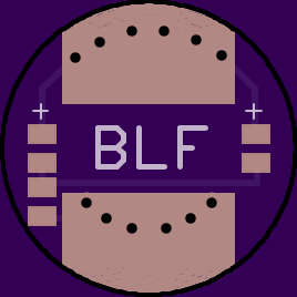
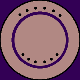
I finally got around to making a smaller version (17mm) of the dual-led board. This will fit lights like the Convoy S series and many others.
Please note I just ordered this myself so it’s technically untested, although it’s essentially the same as the larger board. Also added to OP.
Thanks! I haven’t done it yet, but it’s on my “to do, if I ever get a chance to stop and breathe” list.
Thanks, Pilotdog.
I am finding this board interesting. Could someone tell me what the prices are for the boards, I do not have an account.
I am also wondering how much cutting and such is needed on the S2+ and on the Solarforce lights for install. Or, does enough make it around the switch to get a glow?
Board price is $2-2.50 for 3 boards, free shipping.
I did no cutting to any of the hosts.
I still want to do these, and I ordered the boards a few months ago, but they never arrived  . I will have another go with these now :-)
Edit: ordered, thanks for the update pd68!
Are these boards on RBD's Oshpark thread? If not it would be good to get RBD to add a link there in his OP. I'm going to order a few just for the smaller diameter. Thanks.
I have my parts coming in for a couple of these switches. It looks like a fun project!
I’ve never soldered SMD’s before, so that will be a challenge.
Already an update, the resistors and switches came in from Fastech. Oshpark should be shipping my boards by early next week.
I’m sure I will have questions, if you peoples don’t mind.
My boards just showed up. I'm just waiting on the SMD LEDs now.
Hmm, I can't seem to insert any images today. Will try again soon.
Edit: I think I figured it out.

Good deal
Long ago I ordered these boards before but they never arrived. A few weeks ago I ordered them again few days ago they arrived.
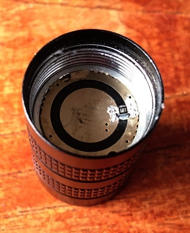
First try on a Supfire S1, I first took out the stock switch which is a different design, I had to add a ring in between the new switch and silicon cover, had to do that anyway because it was to be white plastic for the red led-light to get through, the tailcap was replaced by a transparant one, the pillar was shortened. The brass switch retaining ring is very thick in the Supfire S1, so I had to ream the inside quite a bit to get it clear from the center pad of the pd68 switch board. The new switch was this one, started with testing some resistor values, ended up with 5.6KOhm on the switch board, 680 Ohm bleeder on the driver. The new design board allowed two leds in parallel :-)
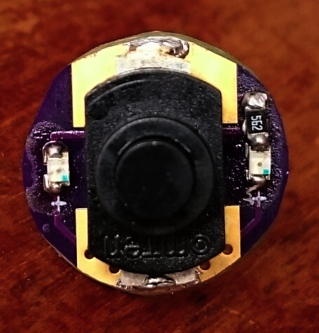
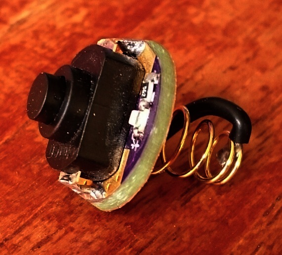
The careful observer will see that in this picture the leds are the wrong way around, they exploded during testing. Actually during testing I blew six of these tiny leds. That will not happen again because now I now know how to do it right.
For the bleeder resistor I drilled a shallow hole in between the batt+ pad and ground ring, so that the resistor was plane with the surface after soldering.
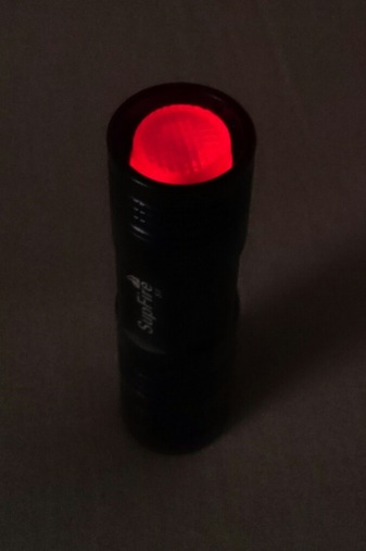

Neat result :-) . I am going to mod this light further (the head is still stock apart from the bleeder R), but this is a nice start. 4V, 6kOhm is 0.65mA, so a 550mA Efest should last about 34 days. I charge it more often than that so that's ok!
Thanks pd68 for the ideas and board, this is a nice little upgrade and a good excuse to fiddle around without having to start on the big hobby-projects that I dread starting, like the DIY contest entry. :sad:
Perhaps as a small improvement, the solder pads for the switch may better not go all the way to the edge but stop a tiny bit from the edge, then there's no chance for them to short against the side of the tail section
That’s pretty fancy, well done pilotdog68! It’s funny that the ingenuity comes more from BLF than from the commercial manufacturers. ![]()
Did you contact oshpark about the missing ones? I presume you also had to pay shipping since you’re not in the usa.
I had thought about that the last time I revised one. Ultimately I had never had a problem with them shorting so I left them all the way to the edge. Shouldn’t be too hard to change that though.
Also, the center pad I left the same size as on the 20mm board so it would be easy to fit a normal sized spring. Do you think I should make it smaller? Or was it juat problematic because of the larger retaining ring?
I’m going to order some of these fairly soon, planning to get a 18350 tube light with Nichia 219 with a good moon light mode and this tail light so its easily found. ![]()