This post is once again about integrating spheres, please feel free to ignore it if you like, it is barely relevant to the flashlight hobby and primarily just my own fixation forced upon you poor BLF-members ;-) .
As with all mod threads, it is difficult to describe unique builds, especially in a language that is not your own, I hope that at least some folks can follow this build (if at all it has your interest).
My other spheres:
Integrating sphere #1: https://budgetlightforum.com/t/-/26542
Integrating sphere #2: https://budgetlightforum.com/t/-/31044
Integrating sphere #4: https://budgetlightforum.com/t/-/33478
 Introduction.
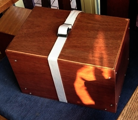
I posted about the 4th integrating sphere before this 3rd one, but at that time number 3 had already seen the light of day ( ). The number three that this post is about was at first supposed to become simple and portable, but during the build I got carried away with adding features... So it did became portable, but not very simple. Now that it is finished it features a 40mm entrance hole (this sphere is not for big lights), a satellite diffusing sphere, a reference light for conversion factor determination (rlcfd, in former threads I called it 'calibration factor comparison light' ->cfc, but I think rlcfd is a more proper name for it), a conversion factor adjustor (cfa), a small led outside for illuminating the luxmeter, and a lid for easy transportation. More info about the features later.
Sphere 3 is going to be made of uncoated finely sanded polystyrene, because during my tests of #2, I was not able to give definitive proof that a BaSO4/latex mix did a better job at reflecting all wavelengths equally well than plain polystyrene: the coating did make a difference but I could not proof it was for the better. And in the end flashlights of varying colour temperature measured very close to the same value with or without coating: from 3000K to 6500K the difference was only 2.2%, from neutral to cool white only 0.7%. For single colour leds the difference went as high as 10%, still not that worrying.
This is a small sphere, and I learned from sphere #1 that in a small sphere, a luxmeter with maxiumum range of 200,000 lux gets already out of range under 800 lumen, and I sure want to be able to measure more than that. In sphere #1 this was solved by placing a grey filter before the luxmeter sensor. In sphere #4 the light is measured through the wall of the sphere. During the thinking process for this sphere (thinking, as usual, took more time than the actual build) I decided on a more exotic solution: a satellite sphere (as I and others also mentioned in other threads, Labsphere has a fine lecture on the theory and the consequences of theory on building of integrating spheres). A second (smaller) sphere was attached to the exit hole of the primary sphere, the luxmeter sensor was placed in there. The (already integrated) light coming from the small surface area of the exit hole of the primary sphere is thus distributed over the larger inner surface area of the secondary sphere, so less light ends up on the sensor. The added bonus is extra integration of the light in the secondary sphere.
This sphere is going to have an inbuild reference light, to be able to calculate the correct conversion factor to convert luxvalues to lumen, compensating for different lightsources (different flashlights, bare mounted emitters) in the entrance hole that influence the total reflectivity of the sphere (e.g. large shiny flashlights cause a higher total reflectivity than small matt black flashlights). In sphere #2, I found that for the measured light value it does not matter if the position of the reference light is in the entrance hole or in a 90 degrees position of that. In the 90 degree position it is not in the way of the to be measured light source, but the inner surface of the sphere does need 2 extra baffles.
After it was finished and having done a large measurement session of different flashlights, I was a bit fed-up with doing the correction calculation for the altering reflectivity for the different flashlights, so I opened the sphere up again and solved the reflectivity variation optically by building an adjustable light absorption thing in the secondary sphere. This way I can adjust the total reflectivity of the sphere towards the same conversion factor every time, and thus avoid the extra calculation.
Parts of this sphere are made of polystyrene hobby balls, radiator alu-tape, latex wall paint, hobby glue, architect's foam board, cellotape, a blank cd, a piece of a cd-box, a black permanent marker, some black plastic cap, a satay skewer, and more cheap common household junk. But the use of cheap materials does not necessarily have much to do with the quality of the performance of a build device, as I learned from my (distant) scientific past: if everything is well thought-out and a stable and constant construction is made, any material could do the job. ..Unless you try to sell it of course, then a 'professional look' becomes important.
Now on to the build:
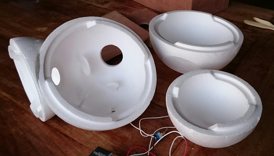
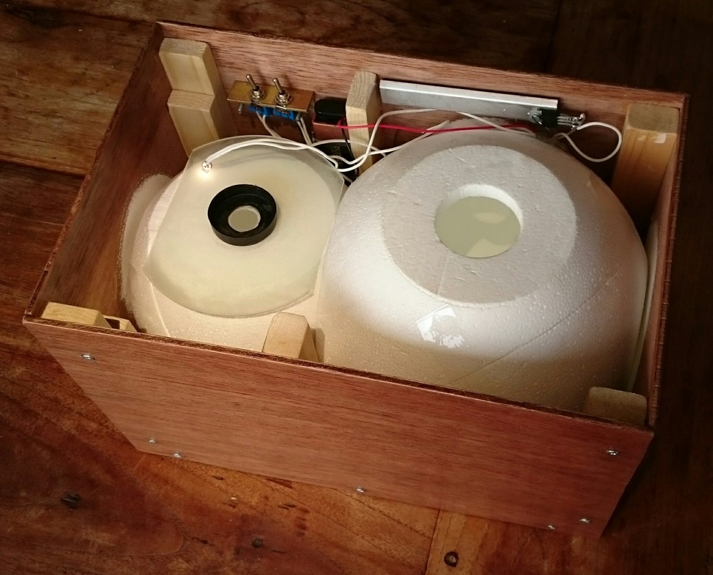
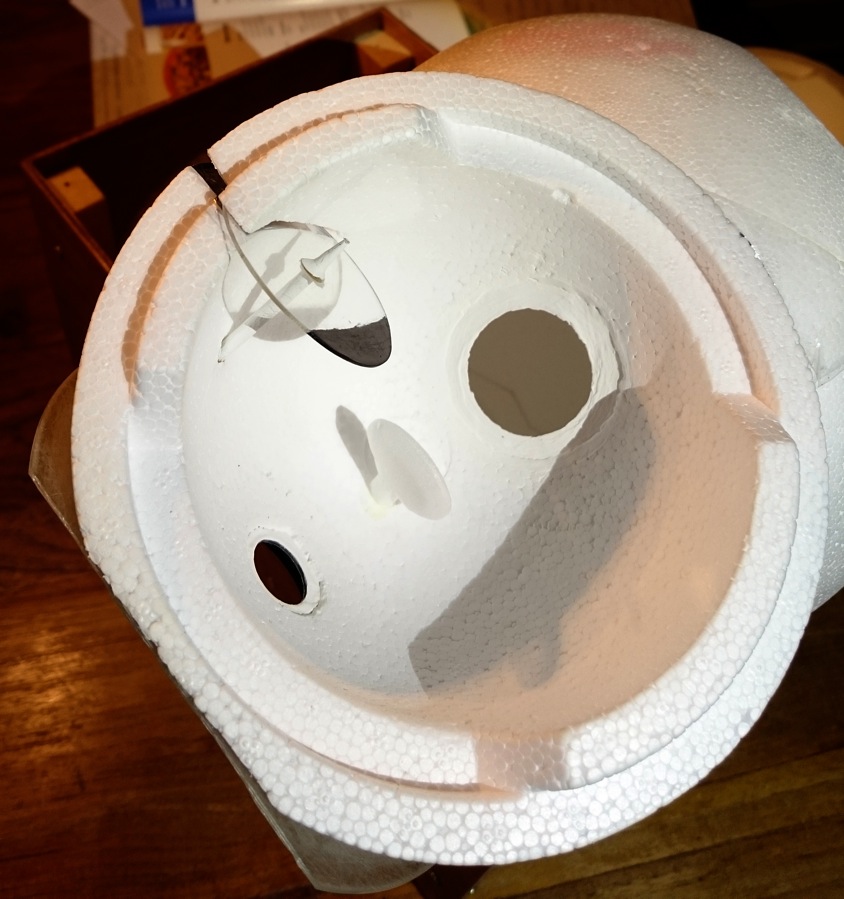
Here, the two spheres (20cm and 15cm outside diameter, 16cm and 11cm inner diameter) are already attached (just the halves are not closed), the surface where they touch is covered with aluminium tape before they were glued together, so that light going from the primary to secondary sphere can exclusively go through the hole and not through the walls. Btw, almost the whole thickness of 2cm polystyrene is adding to the reflectivity of the sphere: light that goes deep into the polystyrene still has a good chance to come out on the inside of the sphere again, I found. Near the hole connecting the two spheres, the greyish alu-tape in the middle of the connection shined through the polystyrene, to recover the reflectivity in that area, some white latex paint was applied locally.
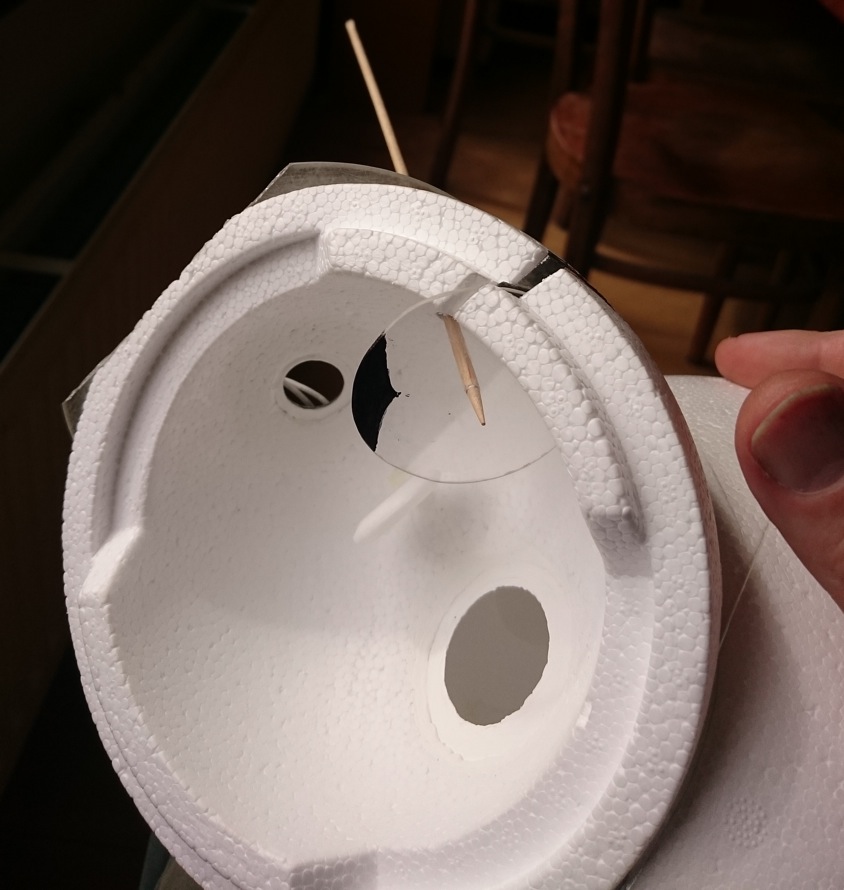
There are four baffles (light blockers) in the device, of which three you can see in the primary sphere: one preventing light from the source entering directly the exit hole, one to prevent light from the reference light to shine on the entrance hole, one to prevent light from the reference light to shine on the exit hole. the fourth baffle is in the secondary sphere (not visible), preventing light from the exit hole to shine directly on the luxmeter sensor.
The hole from primary to secondary sphere has a sharp edge, so that light coming from all positions on the surface of the primary sphere is able to enter the secondary sphere.
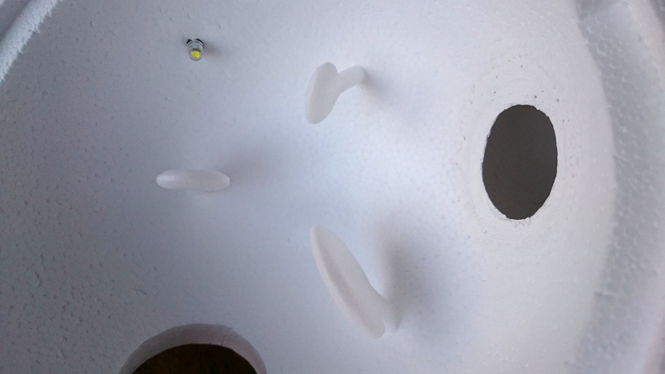
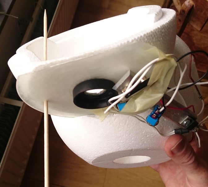
As the reference light, a Nichia 5000K 5mm led was positioned perpendicular to both the entrance and exit hole of the primary sphere, with two extra baffles (from foam board, glued to the inner surface of the sphere) the light from this source is prevented to shine on the entrance hole and the exit hole. To use this led as a reference source, I did some testing to make it have an as constant output as possible, and ended up with this: the legs were connected to lengthy pieces of thick copper wire for heat to escape, the current was regulated at exactly 6.47mA using a 9V block battery and a LM317 voltage regulator (mounted on a strip of aluminium as a heatsink) that together with a 198Ohm resistor was used as current regulator (see for how the wiring goes for example here). The output is now near 3.3 lumen (giving a well significant enough reading on the luxmeter), and is within 0.2 % (!!) constant from the moment of switch-on .
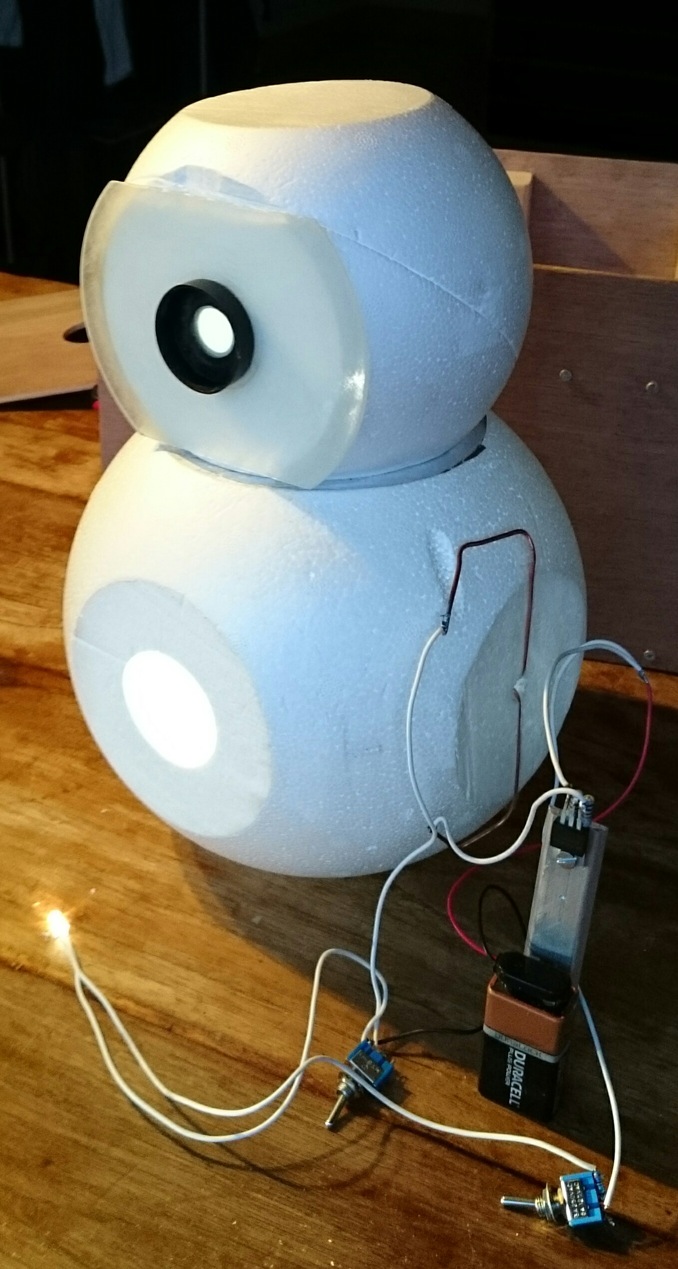
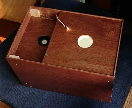
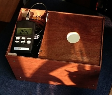
(one-eyed snowman ) An extra led was connected (simply via a 150 Ohm resistor) to the battery to use later as an illumination for the luxmeter read-out. From the secondary sphere, a bit was sliced off to get the luxmeter sensor closer to the inside, and a blank audio-cd was glued on top to give it some rigidness for repeated attachment of the sensor. I found a black soft plastic cap somewhere that fitted snuggly around my MobiluxA luxmeter sensor, I made a hole in it for the sensor to see through and glued it on the cd.
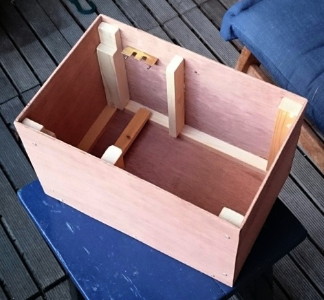
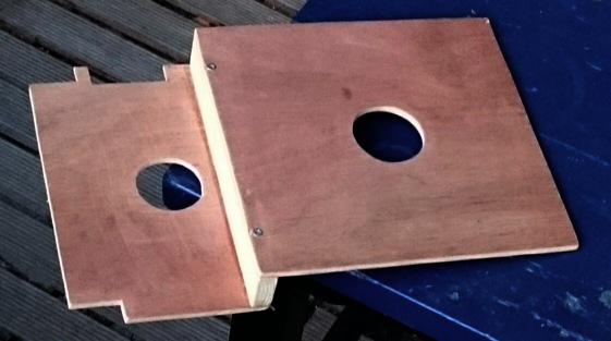
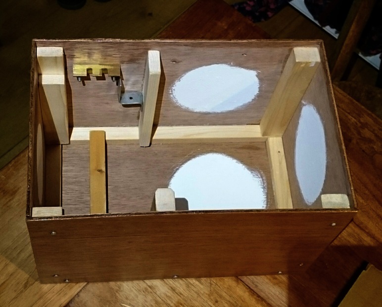
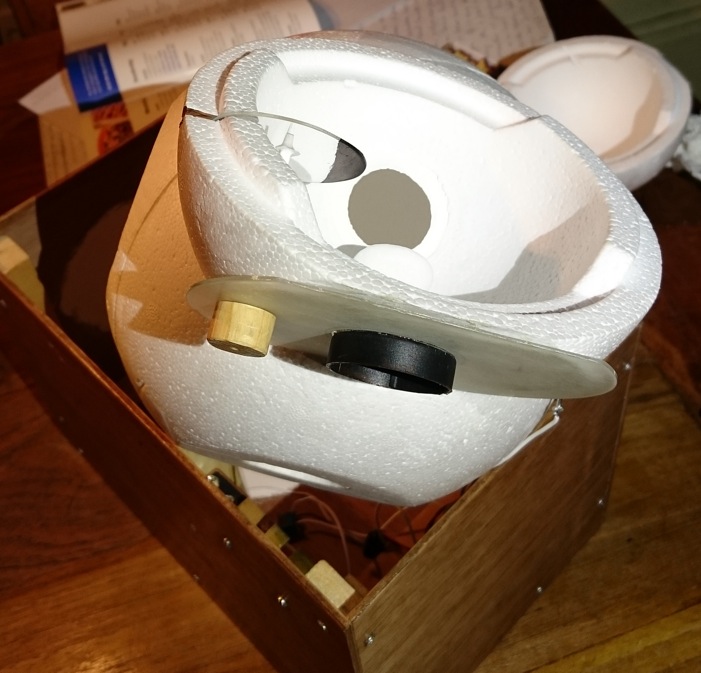
Some more slices were cut from both spheres to make it fit into a smaller case. The halves of the spheres were fixed together with cellotape, which sticks very well to styrofoam. The case was made from thin plywood, small pine timber, screws and glue (and a small piece of brass profiling for the switches, a iron bracket for the 9V battery). I made it so that the sphere assembly could only fit in one single position. Where the spheres touch the walls, the inside of the case was painted with latex paint: because the styrofoam walls are thinner there, the reflectivity is restored this way.
After this was finished and tested well, I added a new feature: conversion factor adjustment by optically altering the resulting reflectivity of the sphere :bigsmile:
I opened the case again and drilled a 3mm hole through the plastic cd to the inside of the secondary sphere, so that a satay skewer would fit through.
A round piece was cut out of a transparant cd-cover, with a permanent marker a section was blackened, a small hole was drilled in the middle and it was slided over the wooden shaft. A slit was cut in the wall of the secondary sphere to make room for the round piece. The surfaces inside the slit were partly covered with aluminium tape to make sure that the blackened piece, when turned out of the way from the inside of the sphere, could not possibly influence the reflectivity of the sphere.
After some initial testing of the range in reflectivity alteration that this device gave, the blackened surface was increased a bit. The round piece was glued to the wooden shaft with a blob of Araldite, and then the shaft was painted white with latex paint.
On the outside, the shaft was glued to a slice of broomstick as a turning knob.
So now the device has an extra knob:
And this is what happens inside the secondary sphere when you turn it:

The knob I can use in the following way: I measure my (known) constant output reference lightsource once (in my case my SWM D40A on high setting: claimed 550 lumen) and determine the the conversion factor luxreading->lumen for it (the conversion from klux->lumen is about a factor 24, btw that makes the maximum measurable output 4800 lumen, the minimum is about 0.01 lumen). Then I check, with the D40A off, what the reading of the inbuild reference light is, and write that down. Now with every following flashlight that I measure, before switching it on, I use the adjustor to match the reference light reading to the written down value for the D40A. If they match, the conversion factor is the same as with the D40A. From now on I have the intergrating sphere calibrated, and can use a constant conversion factor by adjusting the reference light to the same reading every time a new lightsource is used.
I reckoned that the position of the blackened piece was not critical, just somewhere in the secondary sphere was good enough: the bulk of integration is done in the first sphere anyway. I did position it perpendicular to the exit hole of the primary sphere, to make it have its biggest influence after the light has undergone at least one reflection in the second sphere, I thought that this way the integrating properties of the whole assemby were the least affected by it.
I already found out that the numbers generated by sphere #3 are reassuringly constant over a couple of months, and it has the most constant light source that I was able to make thusfar. Now with the newly build conversion factor adjustor I will again have to get used to how good it will function, but trust it to work fine, also over time, I'm happy with it.
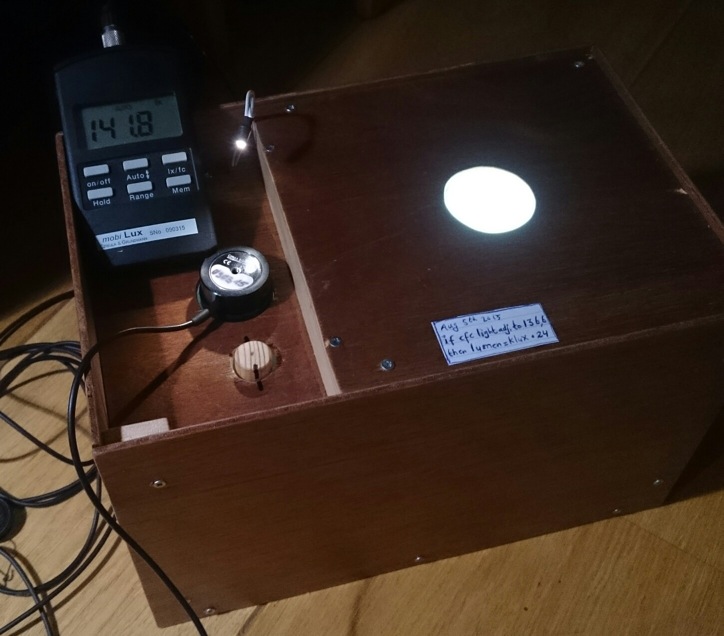
Some numbers to show which amount of variation the reference light plus adjustor will have to solve: The most reflective flashlight I have is the SWM D40A: it snugly fits the entrance hole and has a reflective SS bezel, with the adjustor out of the way the reference light reads 160klux on the luxmeter. On the other side of the spectrum is the narrow Thrunite Ti with matt black bezel, way more light leaks away through the entrance hole or is absorbed by the flashlight body, the reference light now reads 142.3klux. So the shape and texture of a flashlight can cause a 8.9% difference in the reflectivity and thus the conversion factor from luxmeter-reading to lumens in this integrating sphere, that is worth correcting! Btw, reflectivity sensitivity for different flashlights is also a sign of proper integration :-)
In this sphere, the entrance hole surface area is quite large compared to the total inner surface of the (primary) sphere: 1.7% of the inner surface area. In my big sphere (#2) the entrance hole (although in itself larger: 8cm instead of 4cm diameter) is relatively smaller: just 0.75% of the inner surface area, so the influence of the lightsource's shape and texture in the entrance hole is significantly less, e.g. just 1% between the D40A (big with shiny bezel) and the Nitecore P12 (way narrower and black bezel). With the hole narrowed to 3cm (I have an insert for that), the variation becomes so insignificant that a correction with the reference light is not needed at all.
Thanks for bearing another post about integrating spheres