As djozz says. I appreciate the effort as well.
What about paralleling them with blocking diodes in series between each boost circuit and the LED?
+1 ![]()
A good strong boost driver so we can drive 6v led’s with a single battery instead of 2 shorter ones, is one of the few missing things in our ever expanding modding arsenal ![]()
Any updates here?
This is worth a bump from the peanut gallery — just to see if anything shakes out.
At this rate, we’re going to need
a speed loader for batteries …

(with, of course, a supercapacitor to hold brightness while the dead cell is kicked out and the next cell is rotated into position …)
And so, bandoliers of batteries …
What about if only the outputs are in parallel but the internals are separate?
Maybe to a multi die led like mce or XHP where you can power one pair of die separate from the other. With the appropriate mcu different boost circuits could power each die of a color led but that’s a lot of circuit. In any case the advantage of small boost drivers is being able to run an led at low power from a primary cell for much longer than a recharge able li-ion whereas li-ions excel at shorter run, higher current applications. Trying to get enough current from a single alkaline to drive an led hard is like trying to carry a piano up a ladder backwards.
Could 2 pam2803’s be controlled by the at tiny to give two modes each with constant current rather than pwm control of an fet? Would need separate Rsense for each or maybe an ic switch to control separate Rsense only?
Good question RBD. Here are my initial thoughts:
- I barely remember how this works. Let’s see. The MCU runs off of the output from the boost circuit. That’s the weird and magical thing about these drivers IIRC. My memory of this simple circuit will need to be jostled, but that’s the first potential problem that springs to mind. We’ll have to think about this some more.
- Clearly two of these won’t fit into 15mm or course!
- Since you’re asking, am I to assume that nothing better has shown up? 1AA or 2AA boost circuits are still like hen’s teeth? Ugh….
Correct on number three wight. Hens teeth are common compared to the driver outlined.
Switching between two sense resistors could work I just don’t know what ic to use for a low resistance either/or switch. Pwm might add inefficiency to an already challenged circuit. If low enough the internal switch resistance could be deducted from the Rsense values.
![]() Figures. I was hoping that there was some $2 Chinese panacea for this problem by now.
Figures. I was hoping that there was some $2 Chinese panacea for this problem by now.
I don’t necessarily think that it’s a good idea, but IIRC a network of sense resistors and transistors may have been used on another boost driver. Let’s see if we can find it: comfychair - DQG 26650 driver hacking Since all the pictures are now missing from that thread, it is probably pretty hard to follow -> So take a look at these PDFs with the posts + pictures together. ![]() Page 1 / Page 2 / Page 3
Page 1 / Page 2 / Page 3
We could always play around and try something, but probably not in 15mm.
There is a guy from CPF that has posted here about a driver for AA's thats close to being finished but could not find the thread here.
thread de-hibernating… ![]()
I’ll dig up what I got so far.
But allow for a minute or two.
.
Edit:
Every now and then I prodded along with this driver, but with other matters at hand I did not find the energy to post all my ups and downs. Just hoping to lure @wight into this again…
0:)
.
.
So this seems to work.
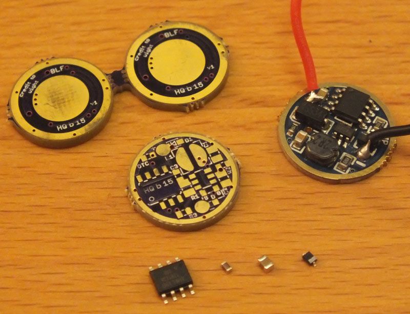
It’s Fasttech SKU1127407 (comes in blue now) with mods.
MCU changed to Attiny13a (which was pre-programmed)
Some MCU-traces cut (Pins1/4/5)
Rewired: Pin6 to Fet-Gate (red wire)
MCU+ is already connected to V+out
Rewired: MCU- to GND
MCU- of the original driver is connected to Fet-Source/PAM3. This did not work with the Attiny, it wouldn’t change modes.
Rewired MCU- to GND (black wire) and voila: 3-mode boost driver that did survive several 1AA and 2AA drains.
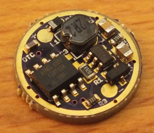
Still don’t know what the 2 resistors (103 / 18D) really do…

.
.
-Unfortunately this did not work out…
Modes do change, but output is flickering in all modes.
(just no time for debugging atm… ![]() )-
)-
((( EDIT: Rebuilding it did work, see posts further down )))
.
Not that one Tom E. It was a low voltage driver that was nearly completed.
I think this is the same driver on CPF.
Would be nice to see that Fastech driver stripped and a schematic of the oshpark board.
@HarleyQuin - That looks like a bunch of good work.
- As you pointed out way back (nearly a year ago
 ) in post #23, there is clearly a problem with my BRD (actually with my schematic). My schematic is very poor, but I have only myself to blame. I don’t think that I confused PAM2803 with PAM2805, but maybe I did? Who knows. I didn’t actually create PAM2803 a part in Eagle, I used another part with the same footprint. Maybe that’s how I got confused (all pins are labeled incorrectly of course ;
) ). In any case, you are correctthe output cap should be elsewhere. - Looks like you’ve done all the hard work for us.
- It’s too bad we can’t do better than 370mV, but at a glance you do seem to be right! With that in mind this inexpensive diode seems to be a good selection for the project.
I went ahead and ordered 3 fresh donor boards from FT.
Does anyone in the USA have a few of the schottky diodes to spare? I don’t want to mooch, but I also am not ready to place an order with Mouser/Digikey at the moment. I’d be happy to trade something to cover the parts and postage (mosfet(s), 7135(s), PCB (s), etc).
Dang Alex - you mean the standard diodes we use on our regular Atmel based boards? Just got in 100 from Mouser, so I will gladly send you a few. Can't get them in the mail til tomorrow AM, but don't you dare try to send me anything for payment .
Please pm me - I'd love to help you out - least I can do...