New Driver: PD68 "DoubleDown" - 17/20/22mm FET+4

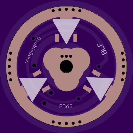
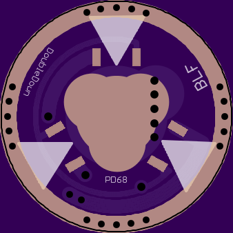
New Driver: PD68 “DoubleDown” - 17mm FET+4

Whenever I am modding a light, it is always a struggle for me to decide if I want the all-out power of a FET driver, or if I want the consistency of a Linear driver. If I choose the linear driver, I then have to mess with stacking 7135’s to get the high mode where I want it.

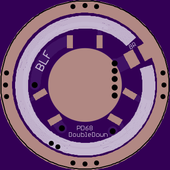
To make things easier on myself, I decided to mix the two of them. Medium is my most-used mode, and for me the sweet spot for medium is always in the 1-1.5amps range. This driver will let you stay in regulation for moon, low, and medium, then access the FET for the highest mode. It will also function as a normal single-sided FET+1 driver if you don’t populate the pads on the back.

I wanted room to fit a 7.5mm spring, so the 7135’s on the bottom are pushed out a bit. This could cause retaining-ring issues, but it was a sacrifice I was willing to make.

I also included pads for a Bleeder Resistor for my Lighted Tailcap project.

The design is heavily influenced by wight’s designs, and others helped answer questions along the way.

This is my first time at making a driver. So if you see something that looks off, please let me know. It is untested as of now, I just placed the first order.

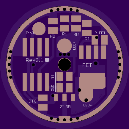
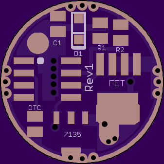
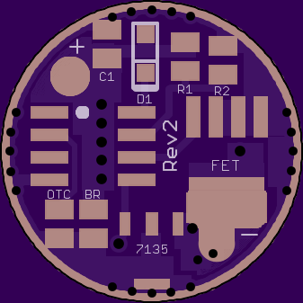
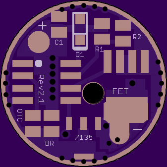
17mm Revision 2 and 2.1 (Current)
Revision 2.1 is the same as 2, but with the MCU and FET pushed more outwards to accommodate a 2.1mm pass-through for an LED+ wire.

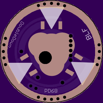
20mm and 22mm Revision 2.1 (Current)
These boards are identical except for the outside diameter. They have all the same features as the 17mm board, plus:

  • LED+ hole is now directly in the center
  • Attiny45/85 ready
  • Separate pad for Pin 3
  • Zener ready
  • Gate pulldown resistor for FET

Oshpark link for 20mm ……………. Oshpark link for 22mm

Revision 1 (Outdated)

Looked it over. Assuming your using Attiny13a (SSU footprint?), it looks good to me. Nothing is jumping out other than the not connected ground pad (as you noted). Nice work there! Wish I was as handy as you with Eagle.

Fantastic!!!!!! I do not know anything about designing the drivers but I sure as hell am extremely happy to see others continue on

One question...instead of an Attiny13...can you get a 25 to fit. Thinking of TK and others with the talent to write code that can do tricks...especially silly code for flashlights LOL

well this one will just be with the 13a because I personally don’t expect to upgrade to the 25 anytime soon. I don’t think I can get the 25 on here, but maybe when I get the physical boards from oshpark I’ll be able to see where I can make up some space.

Edit: wait, doesn’t the Attiny25 come in the SOIC8 package? I was thinking about the 45.

Thanks. I don’t know if I’d call myself “handy” yet; it’s been a frustrating 6 hours. :weary:

the main things I’m worried about:
Is the voltage divider correct?
Do I have enough/correctly placed via’s?

I’m working on moving stuff in a bit more away from the edges

Voltage divider looks good. I can't answer your concern for the via's. I'm sure there are formulas to determine how many and how big they need to be to handle the current they will be moving, but I'm not knowledgeable in that regard.

I believe 3 pins on the FET are ground and since all the current passing through the FET goes to gnd I’d suggest grounding all three with a pour connected to the ring. TP would slap you upside the head for running the pwm trace under the 7135’s and three pads on the gnd ring have acute angles.

what exactly is wrong with acute angles? I am adding a big silk under the 7135’s, both for aesthetics and to help insulate the pwm trace.

The 7135 output trace should be wider(as wide as will fit) as this is part of the heat sinking of the chips as well as the current bus. Eliminate the doglegs in the pwm trace to pin connections. It’s fun puzzling out how to move stuff around isn’t it?

Since there’s nothing in the way you could make the spring pad a bit smaller but connect it to a copper pour under the led+ pad with vias there to make up for anything lost under the mcu. This would allow you to move the bottom side 7135’s inward and give more room for ground tabs to clear a retainer ring.

I really want a 7.5mm spring pad so I don’t have to use those teeny Qlite springs. I actually wanted 8mm, but that wasn’t feasible.

I think it’s done, but I can’t figure out how to crop the workspace size… its a big mostly empty square on oshpark

Yea, you want a thick wide connection to the fet ground pins to keep resistance low.

I’ve fixed almost everything you guys have pointed out, thanks. Now I’m having the issue where oshpark renders a big empty square with the driver down in the corner. What’s the fix for that? other than that, the driver is done.

edit: like this

Check if you have any parts, traces or silkscreen somewhere outside your board, Oshpark automatically crops to the smallest square that fits everything.

~ edit ~
Can’t see your picture.

Less likely imo but it could also be a problem with you cam job. Oshpark provides a cam job here.

I don’t see anything that should be a problem from your screenshot.

Thanks for the help guys, I’ve changed most of what you suggested and cleaned stuff up a bit.

OP updated

If you can’t find anything that could be causing the problem then I could take a look at your .brd file. You can add the .brd to the zip file that contains your gerbers, upload to oshpark then share. Oshpark just ignores extra files in a zip, it only uses the gerbers when a zip file is presented.

~ edit ~

Opps. :open_mouth: Looks like you fixed it.

Yep, it was the dumb limit box eagle makes. I thought I had deleted it, but apparently I only deleted one layer of it. All is well now

Looks nice. Thanks for the effort and for sharing, pd68, you continue to amaze with nice innovations.

To me the 7135 pads on the bottom look pretty close to the spring pad, but I’m far from beeing an expert, and I understand why you wanted the spring pad as big as it is.