If you can’t find anything that could be causing the problem then I could take a look at your .brd file. You can add the .brd to the zip file that contains your gerbers, upload to oshpark then share. Oshpark just ignores extra files in a zip, it only uses the gerbers when a zip file is presented.
Looks nice. Thanks for the effort and for sharing, pd68, you continue to amaze with nice innovations.
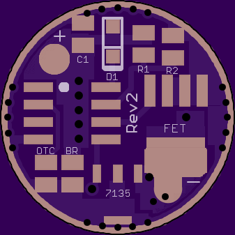
To me the 7135 pads on the bottom look pretty close to the spring pad, but I’m far from beeing an expert, and I understand why you wanted the spring pad as big as it is.
Acute angles like the one at the gnd ring of the OTC can cause acid traps and result in poor rendition of the board or at least so I’ve been told. Acute angles become places where the copper might get over etched resulting in a broken trace. Try thinking in terms of removing a minimum of copper to create the traces and separations and you will be headed in the tight direction.
nice improvements, pd! You think one could drill through the board and run a wire from withinside the spring to led+ on the mcpcb? Would it even make sense to run that wire directly from the top of the spring to the mcpcb? I think I would try do that and solder the MCU on afterwards
I don’t know what the experts would say and I really would like to know, hope there’s some feedback from other guys. To me, that looks nice. I think this also would come in handy when doing piggybacked driver setups.
The driver needs it’s own batt+ connection, so for when you’re piggybacking drivers you’ll still need to connect a wire or something to the springpad.
I don’t like when the hole is the only led+ connection or when it interferes with soldering the spring to the driver, but it seems like it would be ok how i have it.
I agree, I was expecting more feedback, but then again it’s only been 4 hours since I posted Rev2
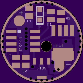
Do you have Mattaus cam generator job? Also use I believe it’s called outline in eagle as the cutoff ring for dimensions…I see you are up to rev 2.1 at OSHPark… great job by the way, loving thes dual output builds!
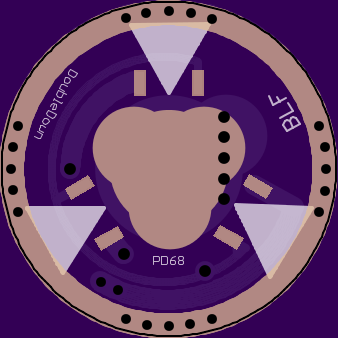
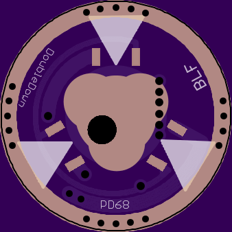
I think most people would prefer the look of the version without the hole, so please don’t keep it like this just for me. I like to have holes in these boards, because I think it’s easier to solder and makes a stronger connection when wires are through-hole soldered. I thought having a hole inside of the spring would make bypassing these easier, but I also like the way led4power had the led+ connection on his ld-1 driver, where the hole comes out outside of the spring.
Just to be clear, it isn’t really going to work for through-hole soldering. There isn’t any electrical connection on the top of the hole. It is just a pass through for insulated wire to go straight from the tip of the spring up to the mcpcb. Some people like that because you get less resistance from the traces in the driver.
I’m definitely in favor of this design feature when space permits but skip the led+ pad and let the spring carry only mcu current. Run the bypass straight to the led. You would no longer need so many vias or thick traces for B+ Either.
I like the flexibility of still having the LED+ pad. Using the bypass hole is better for performance, but I personally think it’s less convenient, so I’ll probably only use it 20% of the time.
Anyways I cleaned up Rev2.1, so it should be ready to go if someone wanted to order it.