The driver needs it’s own batt+ connection, so for when you’re piggybacking drivers you’ll still need to connect a wire or something to the springpad.
I don’t like when the hole is the only led+ connection or when it interferes with soldering the spring to the driver, but it seems like it would be ok how i have it.
I agree, I was expecting more feedback, but then again it’s only been 4 hours since I posted Rev2
Do you have Mattaus cam generator job? Also use I believe it’s called outline in eagle as the cutoff ring for dimensions…I see you are up to rev 2.1 at OSHPark… great job by the way, loving thes dual output builds!
I think most people would prefer the look of the version without the hole, so please don’t keep it like this just for me. I like to have holes in these boards, because I think it’s easier to solder and makes a stronger connection when wires are through-hole soldered. I thought having a hole inside of the spring would make bypassing these easier, but I also like the way led4power had the led+ connection on his ld-1 driver, where the hole comes out outside of the spring.
Just to be clear, it isn’t really going to work for through-hole soldering. There isn’t any electrical connection on the top of the hole. It is just a pass through for insulated wire to go straight from the tip of the spring up to the mcpcb. Some people like that because you get less resistance from the traces in the driver.
I’m definitely in favor of this design feature when space permits but skip the led+ pad and let the spring carry only mcu current. Run the bypass straight to the led. You would no longer need so many vias or thick traces for B+ Either.
I like the flexibility of still having the LED+ pad. Using the bypass hole is better for performance, but I personally think it’s less convenient, so I’ll probably only use it 20% of the time.
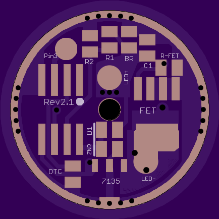
Anyways I cleaned up Rev2.1, so it should be ready to go if someone wanted to order it.
Your upgrades look great. Lot more copper and nice looking lines. I meant to say the first time that I really like the way you organized this driver. Very few long traces. Gonna have to order some next time I place an order.
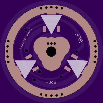
I don’t like using adapter rings or piggy-backing drivers unless I absolutely have to, so I stretched this out to 20mm and 22mm, and added some features.
20mm and 22mm are identical except for the outside diameter. They have all the same features as the 17mm board, plus:
Good news! My order of 17mm Rev 2.1 boards came in today.
When you’re staring at a computer screen working in Eagle, it’s easy to forget how tiny these things are. It’s good to get feedback of exactly how Oshpark is going to produce what I’ve drawn on a screen. Overall I’m very pleased, but here are a few notes:
Notes:
My Turnigy 20awg silicone wire from RMM fit’s just fine in the through-hole, but anything bigger is a no-go. I’m glad I didn’t make the hole any smaller
Everything is a little closer to the edge than I was expecting. There’s still enough room that it shouldn’t be a problem, and I think it is partially Oshpark’s fault (a few things are wonky)
in future designs, I’m going to expose more ground ring on the top (I’ve already done this on the 20/22mm boards)
small fonts and Oshpark are not friends, so some labels on the board are hard/impossible to read
these will work just fine, but next time I’ll make the LED+ pad and FET pad bigger, like Wight did.
D1 is only used if you are actually using more than 1 cell, correct? Also, does it hurt anything to populate the bleeder resistor if you do not have a lighted tailcap installed?