That is sweet. I was planning on designing this very board myself but I’m still in the VERY early stages of using eagle.
This board has everything! Nice work!
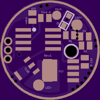
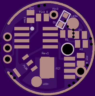
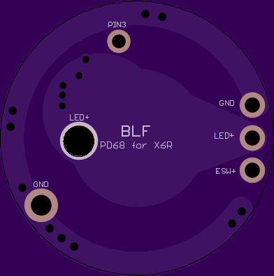
Dang, it sure does look nice! Good to have that pass-thru for LED+ - I've been drilling out the LED+ pad on the wight boards. We found out a little more bout the blinky-mooon mode problem - seems to not occur on some FET's, and occurs on others. Still good to have a pad for the resistor though, as you did. From dthoang:
"I just replaced the FET in the Manker A6 with an NXP PSMN6R5-25YLC and confirmed that the turbo-to-moon flash is gone.
The original FET is marked: 3R030 PBm 1429 C7 9145
My replacement is marked: 6R525L PBm 1502 B5 1981
NXP has two variants of the 3R030: PSMN3R0-30YL and PSMN3R0-30YLD. The PSMN3R0-30YL is the older model still in production, so I’m guessing this is what Manker used.
The dynamic characteristics (capacitances and delay times) of the PSMN3R0-30YL are considerably worse than that of the PSMN6R5-25YLC.
We might be seeing the effect of dv/dt turn on as described here and here."
I’ve been trying to get the grips of it but I’m finding it really difficult. I’m not getting a lot of time to practise either just 30 mins here and there. Hopefully once I get me study all cleared out I can sit down and have a play.
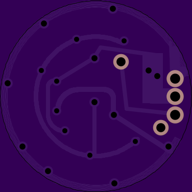
My board is built on a grid with a midpoint of (20, 20)
The radius of the board is 9.925mm (19.85mm diameter)
I took 20 minus 9.925 = 10.075 (outside edge of the board at the midpoint of the vertical axis)
then added the 1.55mm setback from the edge and set the middle via at (11.625, 20)
Then I set the other two via’s on the same horizontal axis 2.36mm apart from each other at (11.625, 22.36) and (11.625, 17.64).
A square with 0.64mm sides has a diagonal of 0.905mm, so I set the drill diameter to 1.1mm to give a litle extra wiggle room.
Does all that sound right? If that’s all correct, then this should be ready to go.
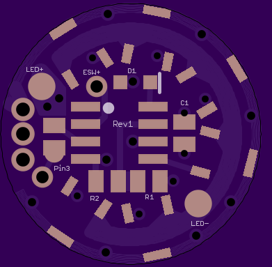
I also enlarged the LED+ pad, and added through-holes for Pin 3 and an extra GND wire, so you can solder them through the bottom instead of running a wire around the side.
Edit: Maybe I should clarify. You don’t need to use the LED+ or GND holes, they’re just there for a lower resistance option. The driver will work just fine if all you do is connect the three main pins and add your emitter wires on top.
Got my 2nd X6R in today from BG - same beat up white box packaging, but breath-taking perfect condition! Love the quality and precision of the manufacturing.
My X6R was delivered today, here are my impressions.
Likes:
- Ano is nice, I like it better than the super matte stuff
- the more aggressive knurling is very nice
- side-button is nicely recessed
- USB cover seems very robust and well-designed
- perfect application for a forward-clicky
the stock UI is actually pretty nice! L>M>H>T with a good Low and well-spaced altogether. Hidden strobe by holding the side switch, and “soft” off with a double click. Mode memory when you turn off on the tail.
Dislikes:
- Clip nubs stick out too much
- tailstanding is a bit precarious like the original X6
- there is some audible whine on all of the middle modes
- works with normal-ish protected cells, but not the super long ones
I know there had to be room for the extra electronics, but I still wish it had deeper cooling fins
Do you think it's a great deal though for $22-$24? I think it's outstanding. Compared to say a XinTD C8 we paid like $30-$32 for, this is looking real good.
True - the stock UI isn't so bad, agree. Im' not a fan of the dbl-click, but it's nice to be able to turn it OFF quickly from the side switch. I've tested them out at about 900 lumens stock, and they use the 380 mA 7135's.
It seems they really thought about the placement of the side switch - it would be hard I'd think to accidentally engage it.
Agree bout the wobbly stand, though I think it's better balanced than the X6's, not as head heavy.