Is the white wire soldered only to the ground ring or is there a via under the tip of it that connects to the led- trace?
Was just about to reinstall 7135. If that works I’ll try w a different type of nanjg, from illumn.
I think the conversion should work but not if you switch the mcu to a different board with different I/O hook ups and you wouldn’t be able to reprogram it.
Lots of members I miss too, those and others.
Hard to tell from the pic but to me it looks like the white wire might be soldered to both gnd and led- which would bypass the FET and lock it in DD.
It is another driver than the 105C, but with the AK-47 I have an original NANJG version that uses a different Attiny pin for the 7135gate than a generic version sold by Banggood. So the lay-out is not always preserved.
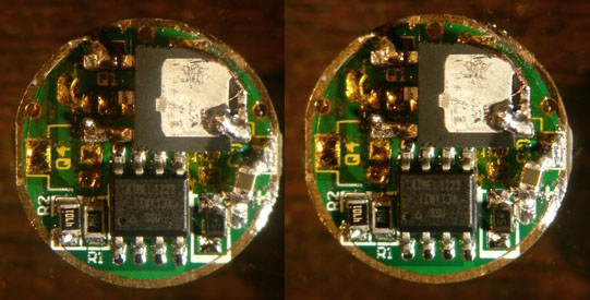
Perhaps a bit useful, here's a stereo picture and a stereo gif that I posted in comfy's thread, they are still there, these are the original 105C board an Vishay FET from the OP of comfy's thread:
RBD, djozz,
If I remove the FET and solder one of the 7135 in, and move the emitter - wire to the normal place on the driver, I get modes.
If I remove the 7135 (again) and solder in FET, and move the emitter - wire to the FET tab, I get no modes.
The white wire is only there to make it easy for me to test, i.e., I hook the - of my bench supply to that white wire and the + from my bench supply to the spring to test. It’s only soldered to the ground ring on the battery side of the driver board (I’ll double check but that was my intention)…
EDIT: I think that I’m concluding that the boards I have don’t work with FETs. The MCU has no markings so I can’t tell if it’s an Atmel.
Hah! So the original mod DID use a 3-pin FET (looking at your images), right? Now I know I’m not going crazy!
But, do you know which FET was used, because in the original the FET was positioned with the ground tab on top (upside down) so I think the Gate pin for whatever FET was used must be the opposite side/end from the AOD510?
That sounds indeed like this FETdoes not work well with the 105C gate-signal, in other words: that goes way beyond my expertise. Rufusbduck, RMM or dthoang know more about FET's.
The original FET wax referred to as Vishay 70N02 . Here's a picture of it right side up, by RMM:

Btw, the middle tab sticking out afaik is also the drain, directly connected to the big tab on the other side.
@ ohaya;
I have successfully swapped out the 7135's for a 70N02 fet on the generic FT board, so I know it will work, at least with that fet.
In fact, I think it was the first fet mod I did back when this was being pioneered by ComfyChair.
It's hard to tell from your photo - do you still have the diode there (hidden by the positive lead)?
Hi,
All I did was remove the 8 7135s, solder in the FET, then move the black wire to the tab of the FET. I remember there was some add’l steps, I think about moving a capacitor, but whas a diode suppose to be moved also? Would not moving those cause the thing not to work with the FET?
Yes, the diode has to be there - I just couldn't see it in your pictures.
What you have done should work, as long as nothing is broken, & it plays nice with that particular fet.
The cap mod was specifically for the feedback/voltage spike that was causing the attiny to reset, but your not dealing with the attiny on the FT generic board, so who knows if it'd good/bad/necessary?
FmC,
The driver I have is FT part#1127403. Is yours the same?
The one I have is a few years old, couldn't tell you the part #.
It looks the same going by your pictures.
Hi,
Sad to report that I used another driver (same type, but a new one). I tested it, then removed the 7135s, then added the AOD510, and re-wired the emitter- to the FET tab, and…. I got the same problem, high and no other modes… in other words, the same result as with the earlier board :(…
Hi,
Just so I’m clear, the essence of this was to:
1) Remove all the 7135
2) Desolder the emitter - wire from the board
3) Solder in a FET, with the Gate of the FET going to the Vdd pin pad of ONE of the 7135 locations and the source of the FET to the ground ring on the emitter side of the driver
4) Solder the emitter - wire to the tab of the FET
Mainly, that should be all right?
Yes
Hi,
Thanks. Even though I’ve already killed (yes, I try to put 7135s back but that was no good) two of my 7135 boards AND two AOD510 FETs, this is still really bugging me, plus I have a light that I wanted to put the FET driver into.
I have two of these:
rather than the “generic” NANJG from FT (now all gone) so I’m going to try just one more time (right) with one of the boards from illumn.com and an AOD510.
I really hope that that works :(!!!
Jim
So the boards don’t work if you repopulate with a 7135 when they worked before? Something else going on there as this should be a reversible operation. It may just take a bit more practice to get the soldering neat enough to work properly. It was like that for me and still is since I don’t come even close to the volume of work done by some here. Too much heat for too long can wreck parts. It’s a bit counterintuitive but slightly higher temp on the tip actually dumps less heat into the components because the solder wets more quickly, especially with flux added.
Please realize I’m grasping at straws right along with you and only trying to point out possible failure points. I mentioned the white wire above, did you ever check continuity for a short from led- to ground?
A tip for removing the 7135’s quickly and easily is to flux the chip pins and have enough solder on the iron tip to bridge all three pins so that the pads all wet at once then swipe the chip sideways toward the board edge to remove the chip. Removal this way goes much faster and dumps less heat into the remaining parts(mcu in particular). Something clamped to the board ground as a heat sink will help protect the mcu as well.