I wonder why it uses software PWM at 2kHz instead of the hardware’s built-in PWM at 20kHz.
You think DJ used Pin 1 for the momentary switch? No real board traces visible and very limited info seems to be provided.
You can use pin 1 as an I/O, even on the 13, but after you do that you can't reprogram it without an HVSP programmer. That's another reason I bought a Dragon.
I’m about to place a mouser order, so I figured I would pick up a few of the 25’s for future use.
Will the ATTINY25-20SSU work, or do I need the ATTINY25V-10SSU?
The 25-20SSU is guaranteed to function down to 2.7V, the 25V-10SSU will run down to 1.8V. The only other difference (besides price) is CPU speed, but for flashlight usage this doesn’t matter. I’m guessing you’ll be fine with the 2.7V 20-SSU, but there is a slight possibility that unpredictable things might happen if your voltage happens to drop below that.
For my 85 projects I only go with the 85V for peace of mind, but I bought them from Farnell that have slightly weird prices. Buying only a few and the 85 is much cheaper, but buying 25 or more and the 85V is cheaper. So I bought 25 of the 85Vs… Cheaper and don’t have to worry about the voltage specs.
I would go for ATTINY25V-10SSU. It’s guaranteed it be stable down to 1.8v. 20SSU only officially good to 2.7v.
I got the 25V's too. I'm running them at 8 Mhz now (still faster than the 4.8 Mhz we used on the 13A's) , so the 20 Mhz capability is pretty useless - I believe 8 Mhz is the fastest you can do on the internal clock anyway.
The only reason to consider the 2.8V version is if you’re going to build a bunch of drivers for 6V LEDs (MT-G2, XHP70). Then you might be able to save a little on getting some. Other than that, go for the 1.8V for peace of mind.
Really, the attiny25-20ssu will probably be fine. Other atmel chips usually work a bit beyond their official spec, it’s just not guaranteed. When problems do occur from running outside spec, one chip may be fine and another seemingly identical chip is unreliable. So I think it’s best to, at least do any initial testing with the 25v.
From Richard's post #163 -- got those boards in today!! Qty 3. Looks real good. think OSHPark expressed them to fill space.
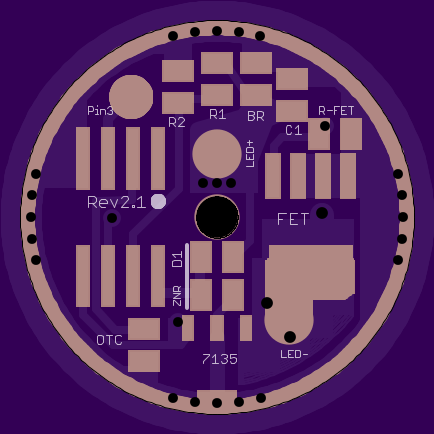
I did a 20mm/22mm version of my DoubleDown driver, and had space to fit Attiny85 pads.
20mm and 22mm are identical except for the outside diameter.
- FET+1 on the top, with pads for 3 extra 7135’s on the bottom (optional of course, for CC med mode)
- 2.1mm LED+ through-hole
- Attiny45/85 ready
- Separate pad for Pin 3
- Zener ready
- Gate pulldown resistor for FET
- Pads for bleeder resistor for Lighted Tailcap


Dang PD!! 
 I'm maybe not miss'n wight so much anymore.
Dam, just realized that I’ve ordered ATTiny25 ![]()
Need to order some ATTiny25V going to have to wait for them to turn up. Now the long wait begins.
Anybody have any good places to get some?
Farnell: http://uk.farnell.com/
I don’t know if they sell to private people in the UK though, I have to go through a third party company here in Sweden.
Try them. Often atmel chips can run fine a bit outside of the official spec. Also you can set the clock speed to 4mhz. Slower speeds are recommended for lower voltage range use. I suspect attiny25 non-V will be no problem at 4mhz.
It sounds like I need to spend some time reading the full reference manual for 25/45/85. If it can run at 4 MHz, that would actually make it almost identical to the speed the attiny13a has been using. (if my recent measurements are correct, it appears that our common drivers actually run at like 3.4 to 4.2 MHz, not 4.8 MHz)
Of course, there’s also 6.4 MHz available. That might be a good balance, but I haven’t tried it yet.
In any case, tiny25 (non-v) goes down to 2.7 V… so if you set the LVP to trigger a little higher it should be fine. I’ve only tested one down to 2.7V (not 2.6 or lower), but it worked great right at the edge of its spec.
I only see two choices of internal clock rates: 6.4 Mhz or 8.0 Mhz in the Fuse Calculator: http://www.engbedded.com/cgi-bin/fcx.cgi?P_PREV=ATtiny45&P=ATtiny45&M_LOW_0x3F=0x03&M_LOW_0x80=0x00&M_HIGH_0x07=0x07&M_HIGH_0x20=0x00&B_CKDIV8=P&B_SPIEN=P&B_SUT0=P&B_CKSEL3=P&B_CKSEL2=P&B_CKSEL0=P&V_LOW=62&V_HIGH=DF&V_EXTENDED=FF
Don't think an external clock is an option for us - too many ext. parts, no driver design for that. How is the speed set to 4 Mhz? Maybe there's a divide by 2 option?
I assume it would have to be a clock divider. It looks like the 25/45/85 have clock dividers for all powers of 2 up to 256. This provides a lot of choices for speed.
I thought you could use the Clock Prescale Register CLKPR to get 4mhz.
If I’m reading the product manual correctly, I think that is correct.