Now that I’m close to being ready to burn firmware, I was wondering if there is any other firmware that can be burned to the NANJG MCU that works with a NANJG-92 FET?
Check out ToyKeeper’s flashlight firmware repository.
So my question is if you convert one of these into a FET driver (done it 3 out of 4 times successfully) can you just leave one of the 7135’s (the one at the end of the Atiny13) on to have a FET+7135 driver, then flash it with new firmware to get regulated lows?
I don’t have the flashing stuff yet, so just a question…
See post #61 - Major apparently did that, but I think he also had to mod the firmware.
Not quite. The 7135 and the fet need to be connected to separate pins on the attiny.
I saw that a while back, prior to looking into the flashing. It seems that you have to cut the leg #5 on the Atiny13, then jumper it over to the FET gate. This means the FET gate is not attached to where the old 7135 was attached as a “normal” mod like this is done.
I am unsure how much programming would be needed for this, I am still up in the air about what Dual PWM is…
I do wish Major would have some more pics and a little better explanation, but that guy was working it earlier in the thread…
Thanks for the answers though!!!
I’m just guessing, but looking at the screenshot of the code he took in post #41, it looks like he has one MCU output going to the 7135 (the original output, I think) and then added code to have a 2nd output to the FET Gate input.
In the screenshot he has two arrays, amc7135modes and fetmodes, and I guess the numbers in the arrays correspond to the modes vs. PWM frequencies for each of those inputs?
So, 1st mode, has:
MODE 7135 FET
= =
off 0 0
1 5 0
2 255 0
3 255 56
4 0 255
So do you see the logic there?
In mode 1, 7135 PWM is 5, and FET PWM is 0, i.e., only current via the 7135 and at low PWM.
In mode 2, 7135 PWF is 255, and FET PWM is still 0, i.e., still only current via the 7135, probably at max, or 350mA.
etc.
Something like that anyway :)…
So, it seems like what he (Major) did was:
1) Remove all 7135s except one of them
2) Add the FET, wired to MCU pin 5
3) Mod the minidrv firmware
Kind of cool hack I think :)!!
Jim
Hi,
I have some of these drivers coming from FT, someday soon:
https://www.fasttech.com/p/1186300
From the reviews, it’s unclear exactly what exact version, but the ones in their pics on their website shows a small cap on the battery side/spring side of the driver. Assuming that’s the case, can someone tell me if I can move that cap on to the emitter side of the driver after I clean off all of the 7135s and have added a FET? And, if so, exactly where (since the pics from comfy’s original post/thread are gone now)?
Thanks,
Jim
Between positive and the ground ring.
It looks like you’re in the USA. Have you thought about getting some oshpark boards instead? For those in the usa it’s easier than hacking up nanjg boards imho.
Ok, thanks for the info about the cap.
The nice thing about using the NANJG board is I don’t have to go buy the different parts (including the MCU), but I just did one where I am also burning firmware and it’s a pain because at least the way I do the FET, it gets in the way of the SOIC clip, so I have to desolder when I want to re-burn firmware. Does the SOIC clip fit on the MCU on the oshpark boards without removing anything?
Thanks again,
jim
Have you tried a hotplate / stovetop?
I think most, if not all, oshpark boards designs should take the space for a clip into consideration.
Hi,
No, I currently use a heatgun for desoldering and reflowing.
I may do what you suggest though (oshpark that is)…
Thanks,
Jim
Hotplate makes it easy to transfer parts from a donor nanjg to an oskpark board. A food thermometer resting on it works to keep an eye on the temp.
I accidentally shorted + - of this driver on upper emitter side with reflector (one layer of kapton tape for isolation on reflector bottom is not good enough :) )
So whole flashlight smoked, battery got hot(lasted probably for 10 or more seconds), i got aware when I saw smoke. After that accident:
- switch died
- driver remained working on one mode(high only). I will throw it away but it survived :)
- Led survived
- Panasonic NCR18650PF survived without any issue?? Lito kala says it is fine.
So I just wanted to post my bad experience here. This is good driver and panasonic is one great cell. No explosion and it still works like a champ.
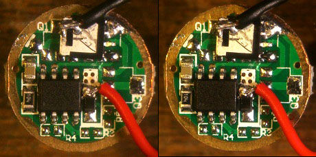
Used Djozz FET driver:
All that current of the short went through the FET, was it the FET that smoked? Or the wires?, If that current was over the FET-specs it may just be permanently shorted. Perhaps if you just swap the FET, the driver lives again. :-)
I potted the driver. Wires looks fine. But I will try to fan de solder all that and see what happen.
Since it works on high only maybe only fake atiny on ak 47 died?
The attiny did not receive an abnormal voltage, so I would not expect it to die. The only abnormal thing that has happened to the driver is a large current through the FET.
^
I agree. if the only problem a reflector short (bypassing LED), the FET, cells, and driver traces would take the hit. Are those protected cells you were using? The protection circuits may allow the cell to work to some degree, but they can mess with mode swiching when they get messed up. I think Ohaya had an issue like that recently. You might want to try different cells, but I would suggest doing an autopsy on the driver first. Makes sure nothing melted and shorted.
You shouldn't need to pot these DD drivers to keep them cool. They don't generate much heat. Maybe you potted to protect wires from vibration?
Yes I potted to save wires from high centerfire recoils. I use AK-47 C (high, mid, low mode). This is the only one of 50 that failed by my mistake. I just wanted to report that to you guys to be more careful than I in building or modding :)
Bats are Pana NCR18650PF (there is no protected version of this cell on the market). I put this cells on discharge test year ago and now this happened and it survived :) . I don't know how but obviously it has some kind of internal protection even without added pcb's.
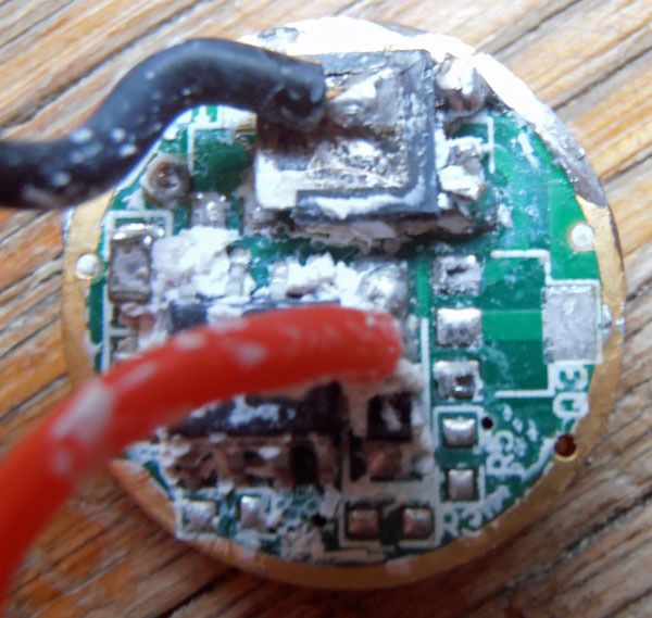
I will have to scrape fujik of driver to see what happened.
I managed to redo fujik treatment. Everything was in place although artic alumina under FET melted during fan de soldering. It seems that FET died since it looks and smells smoked but I did not want to bother replacing with another one. Curious thing is that driver still works on one weak mode.
With this test I found that FUJIK can withstand heat better than artic alumina when we do plastic to pcb gluing like I did with FET before leg and wire soldering.
For metal to metal I don't even doubt AA is far better than Fujik.
So if curing time is not issue I suggest that you put fujik under small FET. Than wait for 24hours for firm fujik cure in warm room, and after that you can finish driver leg soldering and adding +- wires.