Don't think an external clock is an option for us - too many ext. parts, no driver design for that. How is the speed set to 4 Mhz? Maybe there's a divide by 2 option?
I assume it would have to be a clock divider. It looks like the 25/45/85 have clock dividers for all powers of 2 up to 256. This provides a lot of choices for speed.
Just fyi, I'm working on an enhanced e-switch based firmware version that has user selected mode sets only for the 25/45/85 - made a lot of progress on it over the weekend. Right now you can choose 1 of 8 mode sets, mode memory ON/OFF, and lo->hi or hi->lo, so it's probably equivalent to 32 modes of 'guppydrv' style modes. May add more options - the design lends itself to be extendable. Right now it's designed only for FET+1 drivers, and is getting close to 2K of code unfortunately. I was hoping to stay under 2K for the 25.
In testing/debugging, I once again ran into the problem of not being able to download firmware to either a 25 or 45. I'm thinking it's the clip - kind of beat up w lots of use, but also may have to do with the solder job on the CPU pins. I'll try to find a best deal, quick shipment - I know the Pomono I use now I got from DigiKey.
^ Lots of options/improvements there. Hoping Strobe is still immediately accessable from any mode. I think many folks, like me and my wife, that use strobe want it rapidly available. We live in the woods and strobe is quite handy for chasing off most unwanted critters. I would think it could be handy for helping disorient a potential attacker in a city environment. I really like the BLF-A6 FW, but the lack of immediate access to strobe from any mode is a deal breaker for me.
Yes, I'm keeping strobe as it was - direct access via a 'hold' -- I like this as well. I'd like to add options though to choose it or not (maybe beacon), but also extend the hiddens with more than just strobe - this isn't implemented yet. What I have now is to access config settings, 'hold' for a little longer, past the strobe hold time, then light goes off, you get a couple blinks, then you can do 1-8 clicks to choose your mode, then it times out, then 2 blinks, then you can click your next option (lo->hi, hi->lo), then 2 blinks again for the mode memory option -- one click toggles the current setting.
Really you can go two ways: 1-click toggles, or 1-click OFF, 2-clicks ON. Not sure yet which way. Decided to go with the 1-click toggle method for now.
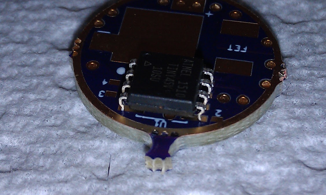
If you want it to fit the Attiny13a SSU footprint, then ideally you want the ATTINY25V-SSU. The "V" version can operate more reliably to a lower voltage, but you would probably be ok with the non-V model.
I personally get "V" versions in the SU package as they generally cost less and I just bend the pins in.
I got the 25V-10SSU, as generally recommended above. It supports a min lower voltage, more like the 13A. The 45V's and 85V's are the other choices - more memory, but wider footprint - not directly fitting most existing 13A drivers, but can be made to fit by squeezing or trimming the pins.
For me, the way it's looking will be the 45V or 85V to get the full UI capabilites I'm looking to do. This of course will restrict my driver board selection, or not, depending...
Yeah, it not only makes the chip taller, it increased the first curve of the pin which makes for a better "grab".
Just make sure you push on that inside arch near the end of the pin. Not on the actual end of the pin. In my first pic above, I pushed on the ends of the pins. That causes uneven leg lengths and the need for adjustments to get the pins to rest on the board evenly. You really only want to bend the pins once and then reflow to the board. After bending the pins, I wouldn't connect a programming clip until the chip is reflowed. The legs are much stronger soldered to the board. I may be being too cautious, but I don't like losing MCU's.
If that bothers you, imagine upgrading the hardware of a fleet of big rack-mounted cellular servers, each with 8 cells and 2592 pins per cell (20736 pins per server), requiring quite a bit of force to remove and insert each cell. Bent pins happened rather a lot. It’s fun trying to fix a single bent pin in the middle of a 48x54 grid deep inside a dark narrow cell slot. Especially when the cell guidance rails have poor tolerances due to being early prototypes, so where they land is somewhat random.
I’m glad I don’t work in a “big iron” data center any more.