Yes, I'm keeping strobe as it was - direct access via a 'hold' -- I like this as well. I'd like to add options though to choose it or not (maybe beacon), but also extend the hiddens with more than just strobe - this isn't implemented yet. What I have now is to access config settings, 'hold' for a little longer, past the strobe hold time, then light goes off, you get a couple blinks, then you can do 1-8 clicks to choose your mode, then it times out, then 2 blinks, then you can click your next option (lo->hi, hi->lo), then 2 blinks again for the mode memory option -- one click toggles the current setting.
Really you can go two ways: 1-click toggles, or 1-click OFF, 2-clicks ON. Not sure yet which way. Decided to go with the 1-click toggle method for now.
If you want it to fit the Attiny13a SSU footprint, then ideally you want the ATTINY25V-SSU. The "V" version can operate more reliably to a lower voltage, but you would probably be ok with the non-V model.
I personally get "V" versions in the SU package as they generally cost less and I just bend the pins in.
I got the 25V-10SSU, as generally recommended above. It supports a min lower voltage, more like the 13A. The 45V's and 85V's are the other choices - more memory, but wider footprint - not directly fitting most existing 13A drivers, but can be made to fit by squeezing or trimming the pins.
For me, the way it's looking will be the 45V or 85V to get the full UI capabilites I'm looking to do. This of course will restrict my driver board selection, or not, depending...
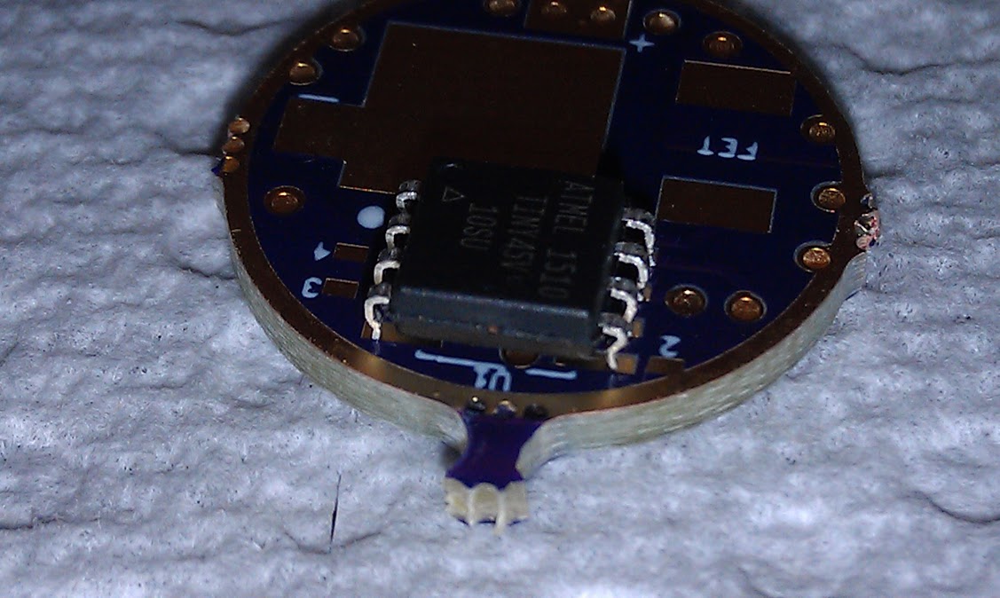
Yeah, it not only makes the chip taller, it increased the first curve of the pin which makes for a better "grab".
Just make sure you push on that inside arch near the end of the pin. Not on the actual end of the pin. In my first pic above, I pushed on the ends of the pins. That causes uneven leg lengths and the need for adjustments to get the pins to rest on the board evenly. You really only want to bend the pins once and then reflow to the board. After bending the pins, I wouldn't connect a programming clip until the chip is reflowed. The legs are much stronger soldered to the board. I may be being too cautious, but I don't like losing MCU's.
If that bothers you, imagine upgrading the hardware of a fleet of big rack-mounted cellular servers, each with 8 cells and 2592 pins per cell (20736 pins per server), requiring quite a bit of force to remove and insert each cell. Bent pins happened rather a lot. It’s fun trying to fix a single bent pin in the middle of a 48x54 grid deep inside a dark narrow cell slot. Especially when the cell guidance rails have poor tolerances due to being early prototypes, so where they land is somewhat random.
I’m glad I don’t work in a “big iron” data center any more.
I wonder how lower frequencies are generated. Simple mechanisms like non-linearity only generate higher harmonics, overtones. Maybe the controller doesn’t keep the 19 KHz constant?
Thanks, will do. Need to order a Pomano 5250 clip also. Just broke mine in trying to get it to work. At least pretty sure I know wut the problem is now - too much solder on the legs, could be the over-used clip also. Think when the solder paste creeps up on the top of the legs, can't get a good grasp. I have a 25 based driver built up for a AS31 light sitting on the stock stripped driver with the switch and was able to get my old clip (black no name) working on it, so can hopefully get some testing done.
I got in my new Pomona 5250 clip now. I still can't reprogram a mounted 25V. I took an 85V, bent in the legs. I can "air" reprogram it over and over again. So I mounted it on a A22DD+1 board, continuity checked all the pins. Looks like a real nice setup for developing with - should be easy to get good contact on the clip. So, clipped it on - the test AVRDUDE command works every time - sees the ID as an 85. But when I program it, it downloads, and fails the verification of the program on the first byte every time - every time over and over. It sure looks like a good clip-on. With the bent legs, looks easier to get a good contact on all the pins. I tried several things - cleaning the pins, shimming it around - I don't know what else to do or try at this point -- out of ideas. Is there something on the driver board circuit maybe interfering with the 85?
This is the error:
avrdude: verifying ... avrdude: verification error, first mismatch at byte 0x0000 0x4a != 0x00 avrdude: verification error; content mismatch
Any help or suggestions are extremely welcome...
Update: Just tried the "-V" option to turn off verification, but didn't help. It proceeded in programming the fuses but failed on each. The driver, also, doesn't seem to work at all.
Update: Also tried another stock 85V in "air" programming it -- works every time over and over again.
You know much more about this stuff than me, but I have to say that it does sound like something in the circuit design is interfering. Which board are you using and does it just have the typical components connected?
Edit: opps, the A22DD+
EDIT2: That is wight's 22mm board, right? I take it you don't have the OTC cap installed.