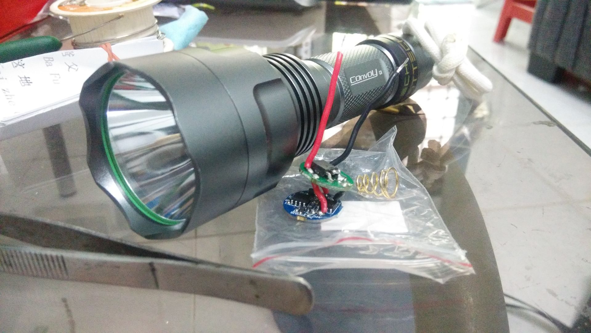
I got this driver from fasttech
I was planning on an upgrade but most recommended drivers I see are from mountain electronics that can never be shipped to Malaysia.
Intl outdoor has some goods and I had some coming but this fasttech driver got me curious for so long I decided to try this out.
(Still waiting for the XML2 U4 1C)
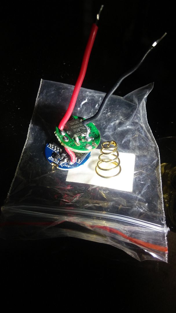
Fasttech packed my driver in their usual format. Small padded envelope with a mini ziploc bag containing the goods itself.
Shipping is ok when you paid for tracking. Within 15 days it arrived. But the other goods that didn’t get tracking is still somewhere past one month.
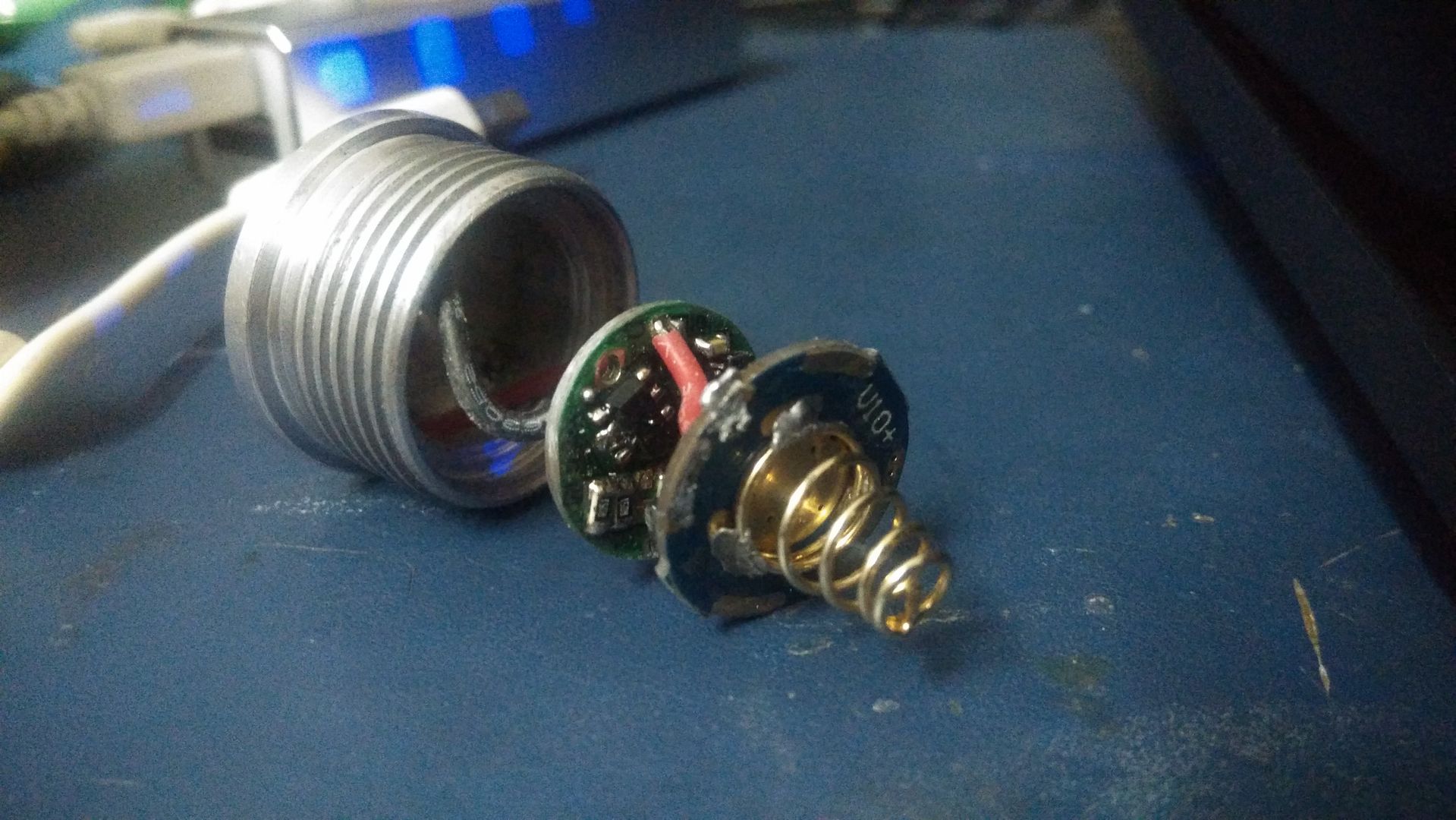
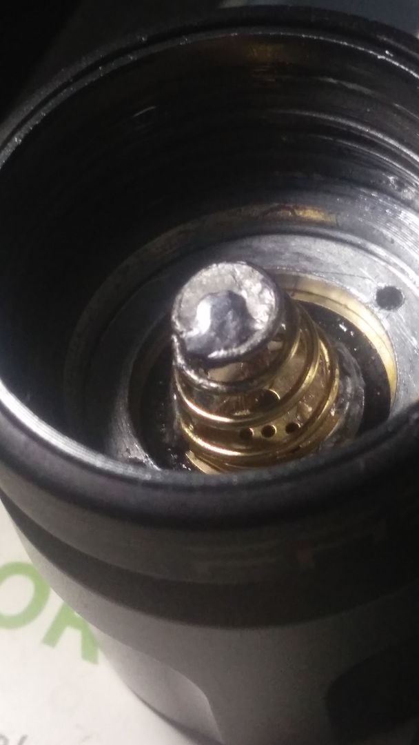
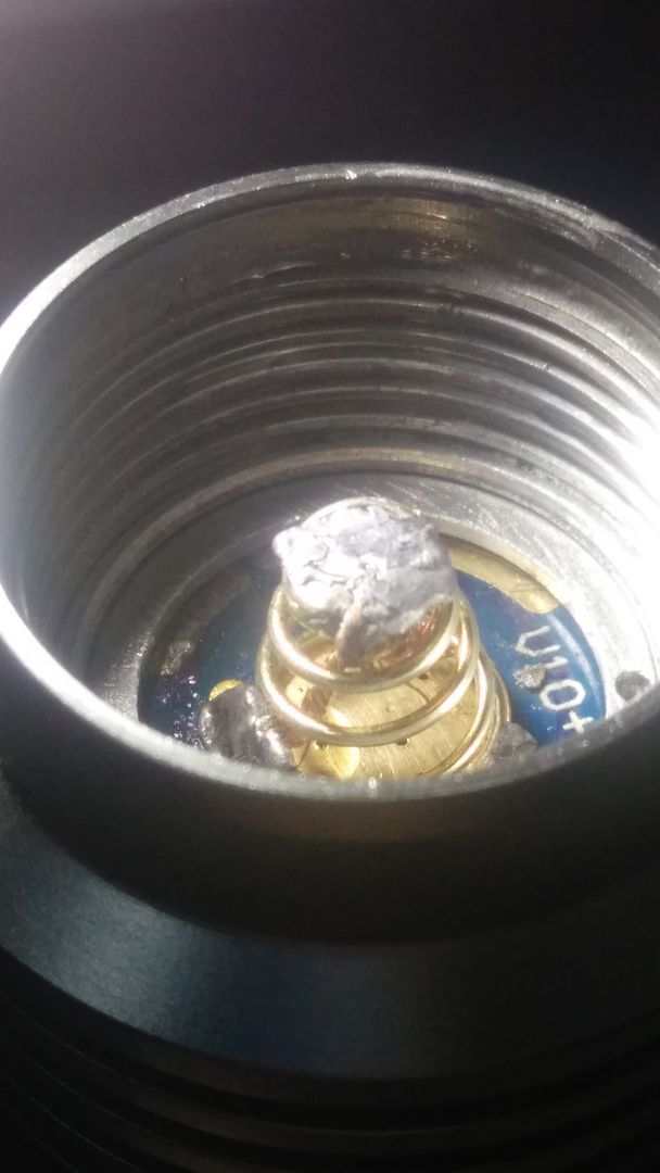
Lots of filing needed to be done on the top smaller driver to fit it inside the c8 pill. I had an extra spring from my p60 mods so I toss them in. Didn’t bypass it as the battery pretty much squish its way to the board. (I did braid the tail though. No pics for that)
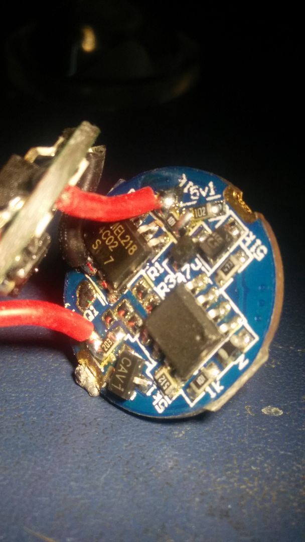

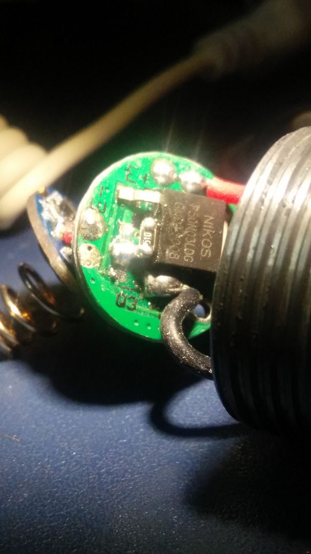
I see a FET looking component in the driver but no idea if it is really is. Care to explain what this driver is all about?
The stock wires supplied are pretty thick wires. I’m glad my soldering iron is able to do its job.
There are a few discussion here (I see ohaya and bibihang) at the end there is a way to make it a direct drive while retaining modes? I don’t know. But if it is possible I would like to try
Details from fasttech said it’s a linear regulator with overheat protection that can deliver close to 4450mA @ 4.2V for the 5000mA driver I got
Probably a good step up from the Nanjg 2800mA driver.
My testing shows a mere 4200mA on high, 1204mA on med, 230 on low (Tested with samsung icr18650-26f with cheapo dmm)
Well that’s some lower than expected amps but it’s probably my battery limiting its power.
Nevertheless it gets this bright and warm fast on high
I get them to toasty hot (around 56 celcius) but the heat protection didn’t kick in. Oh well.
PWM on these is not as fast as Nanjg based drivers but it is not noticeable unless you want to notice it by shaking the light vigorously.
Skipping on to the UI
“Modes:
–100%
*-High 100% > Mid 35% > Low 10% (default)
–1~100 ramping (power off when desire output is reached, and that output is memorized)*
-Mid 30% > Beacon Strobe (10Hz twice, 2-second pause) > Fast Strobe (7Hz) > SOS 100%
“To change mode, go to LOW mode, wait for 3 blinks after 5 seconds, and tap or half press the on/off switch, or quickly power cycle”
They come with off time memory and it is some quick memory. (which can get annoying)
I had a hard time learning how to use the modes on these. I tend to skip groups and it gets really annoying.
The bolded groups are what I called the major groups while the non bolded ones are the “really hard to get there” hidden modes.
A reverse clicky is a must on this type of driver as it involves a lot of quick half presses.
Changing modes are a must in quick taps as clicking it fully is too slow and could give errors like recognizes you in next mode or current memorized modes.
My major gripe is where this driver tends to skip groups and gets into either 2nd or 3rd group.
And getting into 1st or 4th mode requires patience and skill.
Basically.
Group 1 is just 100% so if you are doing full presses you won’t change group.
To change group just wait for the 3 blinks and single tapping will skip to Group 2
Group 2 consists of high, med and low (off time memory around 0.5s)
short taps to switch to high med low
full clicks to confirm modes.
wait for the 3 blinks on low to switch group
(Note: on low, try to wait for more than 3sec after the blink to turn off as it may jump to Group 3)
Group 3 consists of 1-100% ramping.
There is a blink in 50% and 100% and that could get confusing especially when you decided to change group
single tap to enable ramping
full clicking to save desired output.
to change group, save a desired mode (preferably in 20-50% to see the blink visually), wait for the blink and short tap to Group 4
(Just like group 2, wait for 3 seconds after the blink to ensure you don’t change groups.)
(full clicking in between that 3 sec period will jump back to Group 2 and not Group 4)
Group 4 consist of 30, Beacon Strobe (10Hz twice, 2-second pause), Fast Strobe (7Hz) (looks like 10Hz to me), SOS 100
Using this mode is the same as group 2 so there isn’t much to say
Honestly I prefer group 1 and 2 for most of my use.
The brightness spacing on group 2 is well adjusted with low being low and med being actual medium. (nanjg had like med, med high and high)
however on the lows and med it has visible PWM
The lows on the Group 3 ramp doesn’t have PWM even when tested with camera but it isn’t entirely moonlight.
I bought this driver for the ramping feature and I find it useless and totally not practical.
It is very time consuming to use and one slight error and you’ll either fall into ramping or group 2 again.
Group 4 is all out fun blinky and not for tactical use.Maybe it is useful for bike users as the beacon flash and SOS doesn’t turn off the light entirely when it blinks.
The SOS in this light is average. While it pronounce the SOS clearly, they rush the timing in between letters.
Edit:I do not hear PWM whine in my unit.

Overall I would say it is a fun to play driver and not really a useful UI.
Keeping it on Group 1 or 2 is what most of us would buy it for anyway