If moon doesn’t work but everything else does (modes 2/3 and 3/7 should be visibly different from each other), it’s also possible that the 7135 chip could be a different type. The 350mA ones generally have a lower and more consistent moon level than the 380mA ones, and I expect there are more than just two types.
The firmware says to use 2/255 phase-correct PWM, which actually works out to 4 on “frames” in a row out of every 512. Some 7135 chips need 3/255 or even 4/255, and it also depends on the type of emitter. Old XM-L LEDs need a higher moon level than a newer XM-L2 or XP-L.
In other words, moon is pretty sensitive to relatively small hardware changes. This is a lot of the reason why cheap torches generally don’t have moon at all. And if any component changed or was out of spec, it could cause moon to fail without visibly affecting anything else. I hope BG can send you a new driver.
Ha! Cool. You are correct TK. I have many Dr Jones programmable drivers with super low moonlight modes. They are quite inconsistent depending on the hardware. I think you are correct in your theory. Good call.
I'm a bit confused here .. you have two lights that work . why not just figure out whats wrong with it and fix it . they don't all have to lego since they are the same light .what does lego have to do with it and what would you do with an extra couple bodies and a tailcap?..
sounds like you need a body or a taillcap . not three .
at this rate it may just be more prudent to do some work on the tailcap if you can ...it sounds like what you have is a common problem on some of these lights. but what do i know i'm still waiting on mine ( while you guys are having all the fun )
i still reserve the right to complain at a later date ...
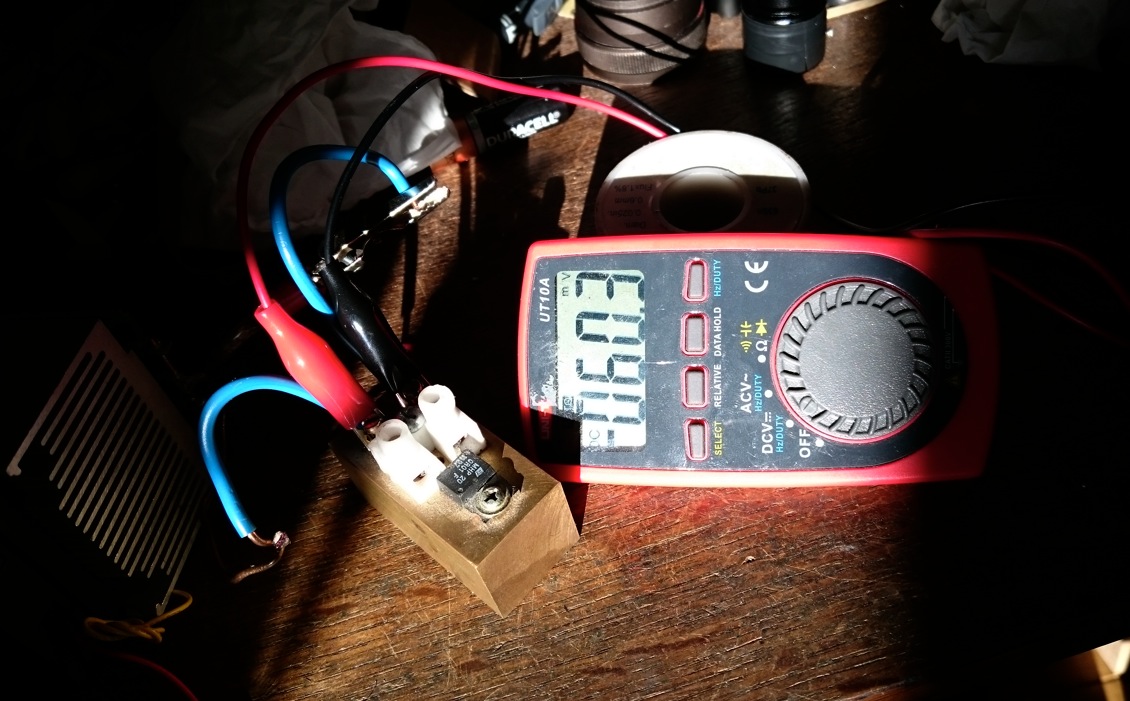
I just checked my current sense resistor set-up with the power supply set at 6.0A (ps reading=not dead accurate, ~0.1 á 0.2 A wrong): voltage measurent with probes directly on the resistor leads: 57.7mV, probes on top of the terminal block connectors (this is where I place the probes for current measurements): 60.3mV, probes at the end of the solid copper leads: 72.0mV. So the whole of connections of the sense resistor gives 2.4 mOhm on top of the 10 mOhm of the sense resistor. so the current drop from a XP-L at 6A caused by the sense resistor in the circuit is about 0.3A.
For perspective, I measured the voltage over a BLF-A6 tailcap with 22AWG silicon wire spring-bypass, measured from the top of the spring to the aluminium ridge that is screwed against the battery tube. When applied 6A, I get 124mV, causing 0.5A drop for the XP-L compared to directly connecting the batt- to the battery tube. So adding a well-build tailcap in the circuit is causing a bit more voltage/current drop, but is in the same range as adding the current sense set-up. That is convenient.
One of the things that is contributing to what burnsd is saying is that the threads on the A6 are anodized, and so the way that the light is designed is that the end of the battery tube at the tailcap end HAS to be able to contact the retaining ring inside the tailcap in order to complete the circuit. If the end of the battery tube is “short” by some tiny bit, it won’t contact the retaining ring and you won’t get any light no matter how tightly you screw in the tailcap (so note that this is not a battery length problem either).
That’s why putting a wire inside the tailcap helps sometimes… basically it moves the contact point of the retaining ring “forward”.
I had to put a wire ring inside my A6 in order for it to work.
I have one of the unanodized A6s coming (it is taking FOREVER to get here) and that should NOT have this problem since the battery tube is not anodized, the contact is made by the threads themselves, rather than by the end of the battery tube contacting the retaining ring inside the tailcap… that’s the theory anyway :)!!
As far as I see it, the A6 tube is not in contact with the tailcap retaining ring (too small in diameter), it only gets in electric contact with the bare (not anodized) part (ring) of the tailcap.
This is one of the things I don’t understand in the construction of the A6 host, the other is the placement of the seal in the head (behind the glass lens).
Yes, “shelf” seems to be a good description for this part of the tailcap.
(English is not my mother language, so it’s sometimes difficult to find the right technical terms. )
Sometimes we get carried away when obvious solutions are right in front of us.
3 solder blobs on the ground ring of the driver, about 10 seconds, and the problem of a short tube is fixed.
I have yet to see one with the contact at the tail cap having issues. Again though, pull the retaining ring on the switch, put 3 blobs of solder on the ground ring around the outer edge, replace the retaining ring, and there should be no problem. A matter of seconds if indeed a short battery tube thread is the issue. Not sure what the answer will be for non modders, but a paperclip bent into a circle and placed under the retaining ring will do the same thing as a few solder blobs and take little more time as far as the tube length issue goes. Anyone should be able to accomplish that one.
I have been finding that this driver they built is sensitive to the 7135 regulation chip. So it could be that chip causing issues. TK is doing a lot of testing on that line, so she’ll probably have it figured out directly.
Is the resistance of a paper clip going to be a problem? I’ve found that I have to tigten the tail cap way to often.
Every time I need a light, tube is not making contact.
You can always find a short piece of solid copper wire, like that in House Romex. The center wire from a bit of cable wire (Television cable, that solid center piece) works fine.
The conductance of iron is lower than brass or aluminium but the path is so short (1mm) that you will not notice (compare to a steel spring: a path length of several cm)
i received my unit but unfortunately i see that the base where is the led, it’s not with thermal paste, or at leats there is thermal paste but it is NOT attached to the aluminum pill of the head, so heat is not dissipate
realista, are you able to de-solder the leads on the emitter star and remove it? You can file off or sand off the edges so the star will fit better and then it will seat properly.
I have no idea why they made the emitter shelf area that tiny bit too small instead of the other way around.
Sorry to hear about the issues.
I gotta say folks, having just recently started working with a lathe (the BLF Lathe of all Lathes) I am learning that every tiny detail MUST be right or the other bits and pieces dont’ fit cleanly. It’s much more difficult than one might think.
sincerely speaking…… i’m not convinced about the power of this flashlight. i compared it with my thrunite tn12 2014 and brightness is EQUAL …. but A6 white temp is something cooler than the “cool” tn 12 2014. The tint is too much cool…
and however i expected to see about 1350 / 1400 lumens as advertised ( and 1600 with mod spring) but i can tell you there is no real difference with 1000 real lumens from the thrunite.
sorry but as “not advanced ” user i only see a flashlightsold at good price 25 usd and about 1000 lumens….maybe i should had ordered the IMALENT DM21 …. at similar price ( after coupon) but at least microusb port and infinite output….
Thanks for all the responses. I’ll try to cover all the points raised.
1. The paperclip spacer (hat tip to ToyKeeper) was a temporary solution to test the hypothesis that one tailpiece was shorter than the other two. In that role, it succeeded. I’m way too perfectionistic to treat that as a long-term solution. But I do appreciate the links to spacers providing a better compromise.
2. The two “shorter” battery tubes are both shorter in an absolute sense. They are specifically shorter in the section from the end of the battery tube knurling to the tail tip. As well, the length of the threaded section of the battery tube at the tail end is shorter.
3. Yes, I am certain the battery tube is oriented correctly. Still, it’s always good to check the easy solution.
4. I was able to combine sections of the three lights I purchased to form three functioning lights. My issues are: a) the concept of interchangeable parts, dating back to the third century, b.c. was violated, and (on a more personal level), b) if part of one of my lights fails in the field, I cannot replace it with the equivalent part of another.
I do appreciate the opportunity of this group buy, and in no way seek to appear ungrateful, or denigrate the good work done by the BLF members behind it. Honestly, thank you all. My issues are with the execution by the factory—??—in manufacturing tolerances, with the manufacturer—Manker—in assuring a wothy output is produced, and good faith of the vendor—Banggood—regarding the responsibility they assume in making these flashlights available to the end-user. I am optimistic about the resolution of all issues we experience. And I genuinely hope they address these concerns; both for selfish reasons and for the good it will do the community and Manker and Banggood.
5. By way of an update, I contacted heyanquing1@banggood.com and am attempting to have appropriately sized replacement parts delivered.
Pending resolution of these matters, I have friends who want to order some of these flashlights for themselves (because they are not getting mine!)
 Or, you know, it could be a symptom of the lunar eclipse which is currently happening outside. Even the real moon isn’t working right now.