Thanks! Yes, you had it right, it was the diode. Replaced it and now it works,it has become a great light. I have a couple more mod pictures, shall I post them here? (if that is not ok, I could make a mod thread)


Thanks! Yes, you had it right, it was the diode. Replaced it and now it works,it has become a great light. I have a couple more mod pictures, shall I post them here? (if that is not ok, I could make a mod thread)
And we have funky light. Well done guys.
No answer, ok, I'll just post them here :bigsmile:
This was by far not an easy mod, precision was required and everything can and will go wrong if you are me, luckily the essential parts stayed alive, I was able to repair it all.
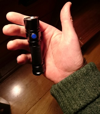
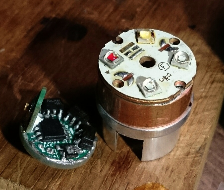
The Solarstorm SC02 is a small and lightweight 18650 light with an e-switch, and it has the correct head diameter for the quad optic that goes with dsche's quad board.
After removing the bezel and lens, the pill can be hammered out with a wooden pole inside the battery tube. From the driver I rescued the little switchboard for building onto DrJones's driver (and later the diode, after I had blown the original one). Pictures of building up the RGBW-driver with e-switch fitted are in post #49 and #52.
For extra rigidity I decided to glue the switch-board in with with AA Adhesive. And I wanted 3 chips per color, FET for white:
 (stereo)
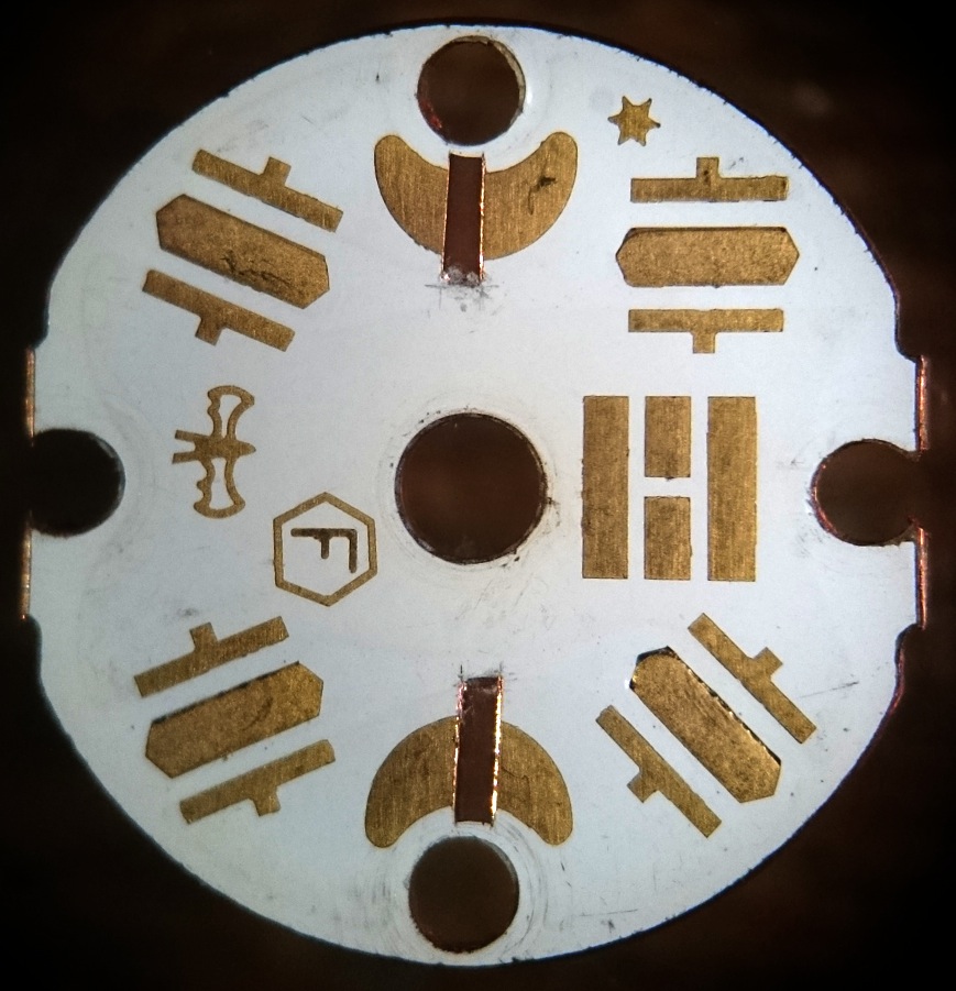
The dsche quad DTP copper board needed adapting for adressing the four leds individually, part of two traces were cut out (new scalpel blade, extra care). I luckily had some experience with that (adapting an XM-L Sinkpad for a XM-L colour), if you go through the dielectric layer, shorts to the core are unavoidable and very difficult to repair, copper on this scale is like a stiff paste! (the dark brown stuff is the dielectric layer)
I made a copper spacer from a piece of 20mm copper rod (sawing+sanding). Measured very accurately the thicknesses and depths of all the parts in the head to calculate the right thickness (7.7mm)
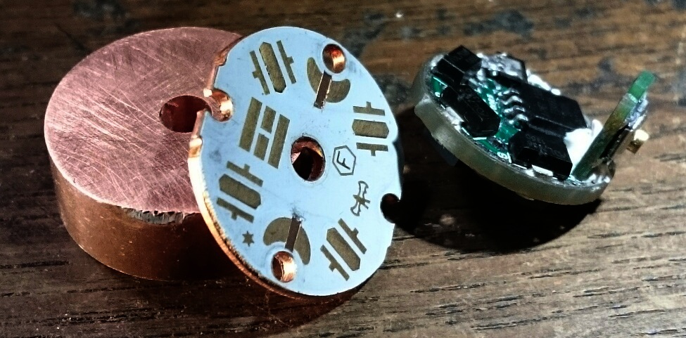
The leds were soldered on the board and at the same time the board was soldered to the spacer by placing the whole thing onto the heat-block. Had three leds not lighting up (shorts to the core) but after replacing it on the heat-block and lifting them up and repositioning the leds, they all worked.
Oh, I wanted a dedomed XP-L at first for the white led (the white route is direct drive with a FET) but I thought the output (1000+lm) would not suit well with the limited output of the colour leds (apart from heat problems in the rather thin-build host). So I went for an old-school Nichia 219A 92CRI that draws about 2A direct drive, 4 times less output but nice tint :-) .
Wires!!!
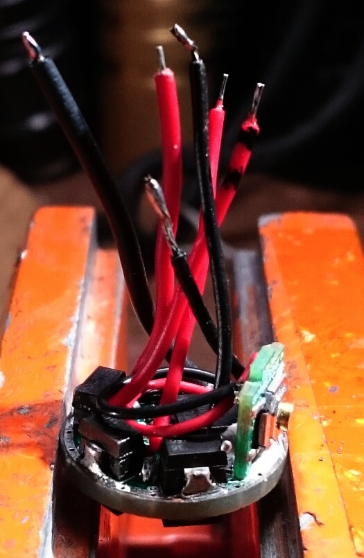
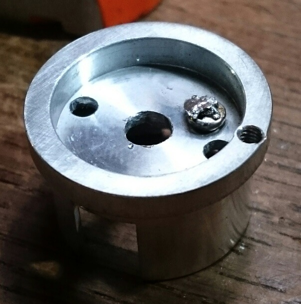
The SC02 stock driver had a ground wire screwed to the pill for contact, I thought it was a good idea to keep that, but the original screwhole was on the edge of the pill where the heatsink will rest, so I relocated it inside by tapping a new M2 hole. Btw, eventually I bored the hole in the middle further out to make more room for the wires. I also carefully reamed the hole in the ledboard somewhat to make space (the electrical traces on top of the ledboard start a bit away from the hole)
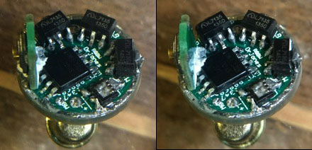
After assembling the lightengine I had a short from the blue-minus to ground (it always lit up) so I had to disassemble again. In the end I put the thing together and disassembling again four times to repair trouble, the last one was replacing the diode that even did not require disassembly because it is on the underside of the driver :tired: . Anyway, after four solder jobs the carnage looked like this:
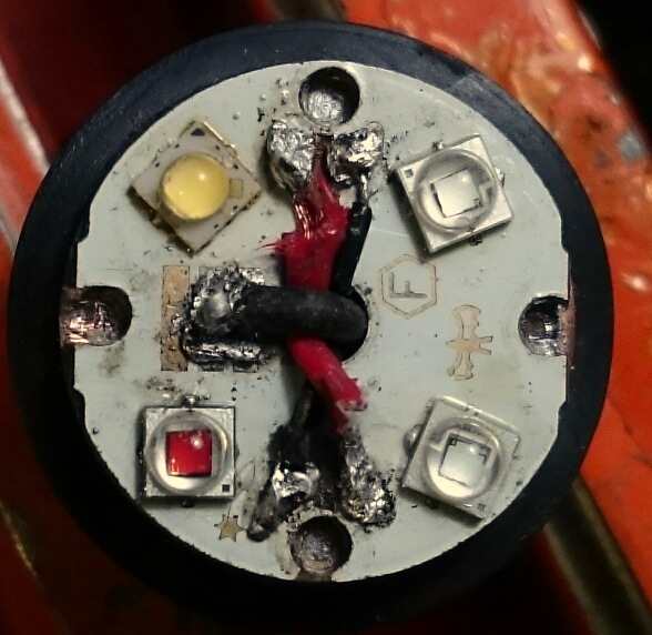
But hey, it now worked! 
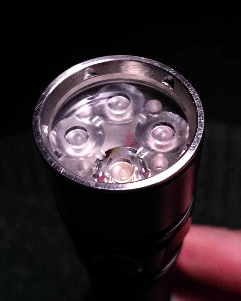
I assembled it with a thick rubber plumbing ring that I had around the copper spacer so that it is firmly kept in the middle of the wider head. The spacer is not fixed to the pill, it is just pressed against it by the bezel (the pill edge was carefully sanded flat, 'flat' is everything in heat-transfer!), heat passes that barrier just fine and I can more easily disassemble the light again if needed. It appeared that the spacer was still half a mm too thin, so I put the stock glass lens back, in front of the TIR. The o-ring does not sit perfectly but it looks fine and it does its job.
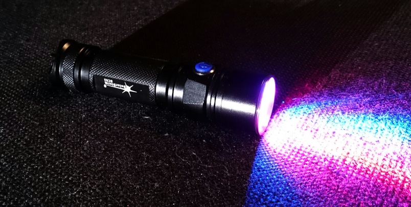

Now the beams that come out of a TIR do overlap nicely but are not perfectly smooth, so colour mixing is not perfect too. So I sanded three of the four TIR's a bit (not the white one!) to smooth the beams out a bit. While sanding he little recessed lenses, by accident I sanded the white lens too  , but that appeared not too bad for the white beam too, it is pretty neat now.
Now colour mixing is pretty ok, while the light still throws a beam.
White on highest setting puts out 250 lumen, lowest setting 0.8 lumen ( ), well done Dr. ! I like the white UI very much, only personally I do not like the memory for white, I would like to always start lowest (ramping up is easy and goes naturally by holding the switch).
While playing with the light for a while (it is irresistable :-) ) I noticed the green is flickering a bit, uh oh, usually such things are the start of worse. So it will be disassembly time again sometime, jay...
That's it, don't try this at home, a very frustrating mod it was, while I want nice and clean and fast mods! ;-)
You make me want djozz. The electrical side of things and the driver would be my stumbling block.
It is a stumbling block for me too, I can do it all, but make mistakes and demolish stuff all the time.
What I would like to do now is do the exact same mod again (I think it is the perfect mod for this driver) but now I know how it's done and I can do it all the first time right and make it nice and clean (dream on, Jos).
But apart from having to get all the stuff together again for that, my time is up: girl+child come back tomorrow from a two-week holiday, I will be a family man again, it can be years before I will have so much time again to spend on the hobby!
Wow. Your wife must really be tough on you.  Mine kicks me out so I can do what I like.
Nice build! I always wanted to do an RGBW quad TIR build, but I never did.
Yes, I know what you mean by 'being a family man' - having 2 small children has a devastating effect on my hobby time - and even in the late evenings, when they are finally asleep, I'm usually too worn out to do anything productive and prefer to relax instead.
It is not that bad, but I have been hobbying an entire week now, like 8+ hours a day. It would even not be healthy to keep doing this, they are rescueing me :-)
You are exactly describing my situation, I have enough energy late in the evening to write some posts but no energy to go building or testing stuff. There is some time on mondays though, with the kid to school, and it is my day off :-)
About the mod above, it looks like it is not good yet: slightly flickering behaviour on various leds, but what is worse, low voltage protection kicks in at 4V instead of under 3. I can't find the source of the flickering, except perhaps a fairly dirty driver board (flux remains). And the flickering can of course cause low voltage detected, but could it also be a wrong type of diode? (The one I use now is tiny and labeled 'S4')
Strange. Measure the voltage across the MCU's pin 8 and 4 (VCC/GND) while running. The diode "S4" should be ok. My assumption however is some bad contact since it flickers. Maybe even board to pill or pill to body.
BTW I have a disassembled SC02 lying around on my desk for months now...
Further checking on monday, I will tip every solder joint with the solder iron, and it is time to replace all wires . The driver-to-pill and pill-to body contact is good.
Are you going to do the quad mod then sometime? :-)
Are you very patient djozz? If so I may attempt this in the future but would need so much help.
DrJones did have the option for an already assembled driver, but I will be glad to help you out :-) (not that the above mod is proof that I'm very good at it  )
)
Fixed
It was the driver to pill connection after all. I had a wire to a little screw in the pill, the screw was leftover from the stock light and made of iron. The solder joint was cold but still sticking well. Replaced with a brass screw and soldered the wire before screwing in to prevent the heat wicking away.
Ran the light with a NCR18650B, the LVP kicked in at 3.27V resting voltage, close enough to empty for me :-)
I'm glad it turned out well :)
Yes, the LVP is at 3.0V under load.
I currently have no concrete plans for a quad TIR, as I have not really the means to make a heatsink-spacer.
I used a piece of 20mm copper bar, a saw, a drill and sand paper (and some patience). I think next time I would use aluminium as it is more lightweight and easier to work with.
Thanks for the help troubleshooting!
Has anyone built the roche f6 with xml rgbw? If so, did you have to file down a 20mm sinkpad down to a 16mm? I read through this thread and expected to hear mention of this, but I did not. So, was curious if the head on my light is different than the older roche f6. I ordered an roche, but I received a convoy f6 instead. I really don’t like that kind of action on behalf of the seller, but the light appeared to be the same so I just let it go. Maybe the led shelf is smaller on mine? Either way, I think I’m going to have to file down the 20mm rgbw sinkpad to 16mm. Ive never done that before. There are a lot of traces to file through, so I will have to find a way to keep them from shorting to the base. If anyone has some tips for me, please let me know.
For sanding down from 20 to 16mm I use a disk sander, the high speed helps preventing the copper from the traces smearing out across the insulating layer. To finish the work I sand a tiny bevelled edge to prevent shorts to the inner edge of the pill cavity.
Ok. thanks for the tips. yesterday, I tried sanding it down with my dermal. every pad was shorted when I was done:) the copper pads and the copper layer under the insulating layer were smeared together as you forewarned. I put on my magnifying headband with the two highest powered lenses and tried to carve a clean cut and scraping away any material spanning the insulating layer. The insulating layer on these rgbw sinkpads is much thinner than a noctigon I filed! Anyway, all the pads are short free for now, but it doesn't leave me feeling good about it.
Need those drivers!!!