From what I can tell the cathode end is soldered next to the - ring on the outside of the driver?
eh? no. What size do you have?
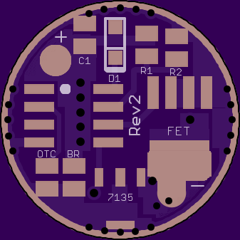
One of the D1 pads has a rectangle around it and is next to the outside ring of the driver the other solder pad has a square around it and is more toward the center of the driver near an MCU pin.
The diode does not connect to the ground ring. The end nearest the ring is actually connected to batt+, and the other end connects to the mcu pin it is closest to.
Nope. Backwards. The cathode, which is marked with a line on the diode faces the attiny.
The inside line making up the “square” is suppose to be the line indicating cathode side.
Instead of a rectangle around one pad and a square around the other pad, you’re actually suppose to look at it as a rectangle around the whole thing, both pads, with a line toward the cathode side.
PD, do you already have a populated driver ready to test? Do you plan any changes to version 2.1?
I would like to order this driver but if in two weeks (for example) a new version pops up I can wait for the new version.
At this point the only thing I would change would be to make the labels a bigger font, but I don’t have any plans to do that right now.
I technically haven’t tested a built driver yet (haven’t had time) but I have checked continuity on the pads with my DMM and everything seemed correct.
If all goes well, I will have one built and tested this weekend. I may only use 2 7135’s on it since I do want it to have a good low ML mode. I will be loading it with a modified version of the BLF-A6 firmware with the blinky hidden modes removed, leaving only TURBO and BATTCHK. I do like going directly from ML to TURBO, so that got left. If I get time this weekend I will run the battchk firmware and will test the LVP on the driver. I am using 22.0K resistor, I do not have 19.1K and did not feel like a separate Mouser order with shipping for 10 or 20 resistors.
I will let you know how it goes!
Matt
Great!
Dang, missed this. Another great job PD! I gotta order some of each.
I got it built and only had a couple of solder bridges to fix, that went well.

Sorry about the quality of this pic...

I used a 560 ohm bleeder and it works with a lighted tailcap. R1 is 22k, that was all I had on hand and R2 is a 4.7k. The caps are the recommended ones for other FET based drivers.
But, now I have other problems. I flashed it with BLF-A6 firmware. I had to raise ML a little, but it is working fine now. I do not seem to have the highest mode, all of the others seem to be there. I also cannot go backwards in the modes. Any ideas? I was able to get into config mode and set it to 7 modes and that works, but no highest output level. I have flashed it with TK's battcheck and it will not run. So, I looked at the code and it looked to me like I needed to swap #define STAR2_PIN PB0 and #define PWM_PIN PB1 for output to the fet pwm channel. This requires me to recompile the code, and it spits out the following errors:
E:\AVRdude\BLF-A6\GccApplication1\GccApplication1\battcheck.c(48,10): error: expected '=', ',', ';', 'asm' or '__attribute__' before 'need'
Hey, you need to define ATTINY.
^
In file included from c:\program files (x86)\atmel\studio\7.0\toolchain\avr8\avr8-gnu-toolchain\lib\gcc\avr\4.9.2\include\stdint.h:9:0,
from c:\program files (x86)\atmel\studio\7.0\toolchain\avr8\avr8-gnu-toolchain\avr\include\inttypes.h:37,
from c:\program files (x86)\atmel\studio\7.0\toolchain\avr8\avr8-gnu-toolchain\avr\include\util\delay_basic.h:37,
from .././battcheck.c:66:
c:\program files (x86)\atmel\studio\7.0\toolchain\avr8\avr8-gnu-toolchain\avr\include\stdint.h(159,9): error: unknown type name 'int8_t'
typedef int8_t int_least8_t;
^
c:\program files (x86)\atmel\studio\7.0\toolchain\avr8\avr8-gnu-toolchain\avr\include\stdint.h(213,9): error: unknown type name 'int8_t'
typedef int8_t int_fast8_t;
^
.././battcheck.c: In function '_delay_ms':
E:\AVRdude\BLF-A6\GccApplication1\GccApplication1\battcheck.c(71,23): error: 'DELAY_TWEAK' undeclared (first use in this function)
_delay_loop_2(DELAY_TWEAK);
^
E:\AVRdude\BLF-A6\GccApplication1\GccApplication1\battcheck.c(71,23): info: each undeclared identifier is reported only once for each function it appears in
make: *** [battcheck.o] Error 1
Done executing task "RunCompilerTask" -- FAILED.
Done building target "CoreBuild" in project "battcheckM.cproj" -- FAILED.
Done building project "battcheckM.cproj" -- FAILED.
Build FAILED.
========== Build: 0 succeeded or up-to-date, 1 failed, 0 skipped ==========
So, until I can get this compiled I am stuck on the voltage testing. I did test battcheck.hex, that I downloaded, on a 105c and it worked. The numbers were fairly high, but I have no point of reference.
Frankly that all sounds firmware related, so you would probably get more help in the firmware repository thread. FW is not really in my wheelhouse. I will say that I’ve also had some issues with the newest versions of TK’s stuff that were made to be interchangeable for the attiny 13a and 25.
Is it just an illusion or is most of the ground ring missing on top?
You need to define "ATTINY 13 "I believe. It's look'n for that or ATTTINY 25. TK set that up in the header file, I think it's in tk-attiny.h
Put:
#define ATTINY 13
somewhere before the header files are included. I'm using her new ltaets header files in my latest 45/85 e-switch code.
I flashed the following BLF-A6 modes…
// PWM levels for the big circuit (FET or Nx7135)
#define MODESNx1 0,0,0,0,56,137,255
// PWM levels for the small circuit (1x7135)
#define MODES1x1 8,20,110,255,0,0,0
And I have 4 low modes and 0 high modes!
I am going to try to add solder to the FET pins in case they are not good.
I did find the solder joint problem, the PWM pin for the FET was not well soldered. Now I get both the 7135 channel and the FET channel.
Pdog, I may have to move to the firmware thread… Just was not sure about the lack of reverse thing. I thought the ground ring was quite thin as well, but it does work when mounted in a light! Right now the off time mode save is advancing 1 mode with each test and I can’t back up. Really frustrating!
I did get battcheck running, got some really odd numbers but did plug them in. Mine were higher than any other sets of files, I was using a power supply. With the unit on battery, it start stepping down almost immediately. Did not you have a problem where the numbers were off when using a power supply as well?
Tom E:
It is defined in the main BLF.c file as the tiny13.
Well your reversing and mode switching sound like the OTC isn’t draining. I’d try it without the lighted tailcap first. If it still behaves the same, try swapping out the OTC for a new one (and be careful how long the heat is on the cap)
My eyes are just shot for today! Not sure I could pull it off right now if I felt like it. I have tried it with both types of tail caps, no change. Will the hot air solder let go with hot air again and still leave usable pads?
BTW, the hole through the middle is just genius!
Matt
Forget my earlier post, I see the problem. You have the parts sideways. I should have marked that on the PCB. The way you have it, the BR effectively doesn’t exist, and the cap is connected to batt+ instead of batt-. And yes, you can heat it back up with the hot air and move stuff around. Did you have any problem with clearance around the small ground ring?

What FET is this this? I would like read about it. I didn’t see a parts list.
It’s basically the same parts list as any of the other fet drivers on BLF
MCU: Attiny 13a/25 or 45/85 for 20/22mm
R1: 19.1k or 22k
R2: 4.7k
C1: 10uf
OTC: 1uf
FET: LFPAK56 footprint