With the light tailcap the only thing not working reasonably well is that fact that mode memory always decreases 1 mode. I can go forward and backwards but just not remember the correct final mode! I do not understand the process for last mode memory. If what I understand is correct, the OTC must totally discharge to store the last mode. It seems to my simple mind that it never discharges while off and therefore considers the off time as a medium press. So, I think I have to get it to discharge more. But, I am not sure if a larger or smaller bleeder will cause that to happen or larger or smaller resistor in the tail cap. Memory works on a standard tail cap.
I see that guys have it working on the A6, maybe someone will chime in with their resistor values.
Gotta hit the rack, will work more on this one. I really like the idea.
Matt
BTW, the center hole is great. It is always hard for me to get the conductor soldered in on the center of the pad.
Hmm… I was able to fit just about everything on the 20mm. Once development gets a little further on FW for the new mcu’s I’ll probably do some with 3 pwm channels.
I have the driver and firmware working and completed. I may add a couple more 7135’s and save this driver for my first triple in a Convoy tube light. Still have to acquire the parts, LED’s, good Noctigon board and spacers for the Convoy. This really screams well regulated medium mode triple!
So to combine notes, just in case someone else runs into any of the issues that I have.
Make sure that the OTC and R1 are in the right orientation. Prevents much head banging!
My build used standard FET+1 parts with a 22k resistor and a 560 ohm bleeder.
I really wanted to use BLF-A6 firmware for mode reversing. I also wanted to eliminate strobe and bike flasher, figured out changes and they worked.
Use offtime-cap.hex, it will save some guess work.
Wanted to use the voltage to adc converter to find LVP and shutdown volts. Had to guess at the settings to some degree. My cheap bench supply must have excessive ripple or a bad wave since values were BS and way high compared to a real battery. But discharging a battery by tenths while the firmware was loaded is not going to happen. Will have to check battery during controlled discharge and adjust firmware in the future.
These values in the “tk-calibration.h” file work very well with lighted and traditional tailcap.
#ifdef OFFTIM3
// The OTC value 0.5s after being disconnected from power
// (anything higher than this is a “short press”) #define CAP_SHORT 235
//was 210, 225
// The OTC value 1.5s after being disconnected from power
// Between CAP_MED and CAP_SHORT is a “medium press” #define CAP_MED 170
// was 170
// Below CAP_MED is a long press #else
// The OTC value 1.0s after being disconnected from power
// Anything higher than this is a short press, lower is a long press #define CAP_SHORT 150 #endif
7) The hole for the LED+ wire from the spring to the LED direct works great, I used 20ga wire.
And finally…
8) This really begs to be a triple! I have not built one yet, but now I will have to.
I do only really find 1 possible negative, and I will test it at a later point. I am concerned about mounting 7135’s on the battery side due to possible tab clearance issues with the driver ring in a Convoy light. But, they may go!
Thanks for reading, hope someone else tries this driver. PilotDog has designed a very well thought out board. I just wish I had those skills. I have tried the software and it makes my head hurt!
Just a note on #7, I’m 99% sure it won’t clear a convoy retaining ring with 7135’s on the back. In those instances it might work to modify the ring as others have done to fit qlite’s, or soldering to the pill may be required.
Ahhh - just browsed thru your OSHPark designs from your sig line. Lots of good things. Well not sure yet what sizes. Need to mod up a 7G10 - probably using a XHP70, might do a Yezl Y3 as well. Right now I know squat about an LDO - don't even have the LDO parts yet. All I know is it's needed for a 6V, 2S cell mod with an e-switch to reduce parasitic drain. Also it replaces the zener, but not sure how it's wired in exactly.
I hope you pcb designers can get something from this. While I dont fully grasp it, sounds like he has made improved libs for Eagle for surface mount components. I hope its useful
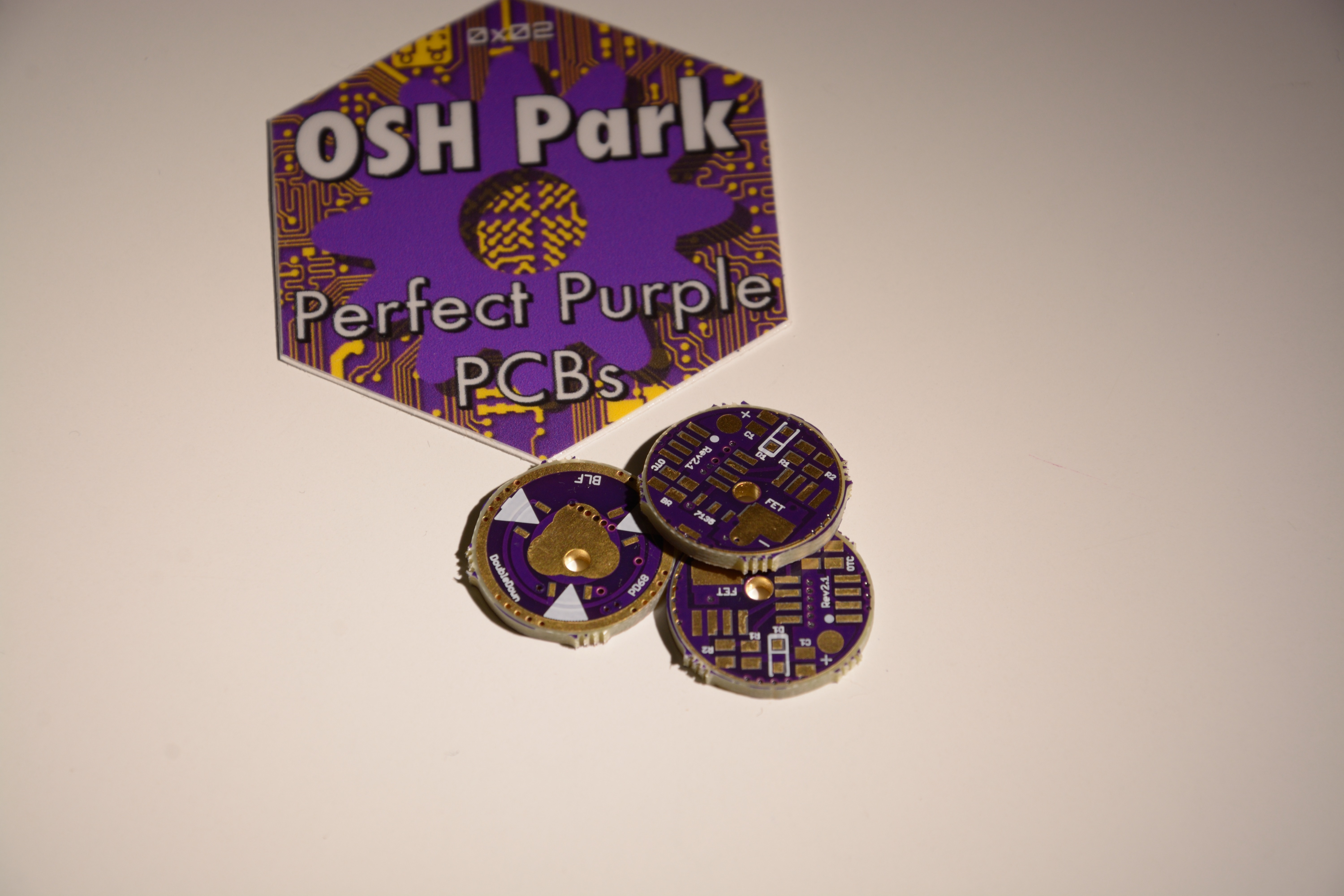
I just received my boards from OSH Park, 3x DoubleDown 17mm rev. 2.1, 3x Triple Down 17mm rev. 1.1z, 3x Triple Down 17mm rev. 2.
PD68, with the DoubleDown 17mm rev. 2.1 the inside of the through-hole isn’t supposed to be plated, right? Cause mine are. Were yours plated? Also from post #57 it seems like mattlward’s boards have them plated on the inside too. I feel that it’s too freakin close to the FET pad and maybe traces coming from the MCU…
I’m gonna try to make some pictures now.
EDIT: From further looking at these boards I must say, I’m not happy with the quality from OSH Park this time. I’ll explain soon.
EDIT2: Don’t get me wrong. I love OSH Park and what they provide to us. Ok, here are some shots. Please excuse that I couldn’t get it closer, I have to work with what I got, and I ain’t got a macro lens.
(click the image to see full size)
Notice the lack of the ground ring on the left side and the weird things going on with the plating of most of the pads?
The only thing that looks to me like it might make the board unusable would be the ground ring. If you can confirm that the ground ring does make contact in your light host, the rest of the board should be functionally okay, though a bit ugly.
Thanks for taking a look and for your feedback, guys. Checked with DMM, no shorts so far. Seems shifted indeed, now that you say it, pyro.
And of course thanks to you PD, for making and sharing these boards. Hope you’ll get a nice firmware for your TripleDown, so many possibilities to use that board.
EDIT: By the way, now when I have these boards in front of me thinking about how to flash, adjust firmware and reflash, and adjust firmware and reflash them… it totally makes sense having an additional LED+ pad. Will use that and move the LED+ wire to the spring at the end.
Looking at it more, as David said the ground ring could cause a problem, and I’m not sure what would happen if Pin1 (the dot) is shorted to ground. It looks close.
I would suggest soldering both your power supply/battery connection to the Batt+ spring pad for testing. Otherwise you will probably have to un-solder the LED+ wire every time you want to reflash. There usually isn’t enough space for the SOIC8 clip to fit with the wire there.
I think I’ll pick the best looking one of the three I got and give it a try - carefully handsoldering. Will finish some other stuff first, but will keep you updated. Thanks
check continuity between Pin1 and gnd, there shouldn’t be any. I’m not positive, but I think there might be a chance of ‘bricking’ your attiny if there is. (maybe someone else can confirm yea/nay?) Pin1 is the Reset pin.