Attiny25/45/85 FW Development Thread

Agree

I do this all the time too, it is like i see what i thought i wrote and then i post it and read it as someone else would read it as just another post in the thread, and I see lots of errors of what i though i expressed and have to edit again………

Me too - I'm guilty of multi-editing posts all the time .

For my 85 driver problem, did a little more testing last night - it's definitely only happening with PWM modes on the FET. Modes for the 7135 only work fine (PWM or full) and the FET full works fine. I did try it on 2 LEDs, not 3, and it's still having the problem. Gotta try this with another driver - really need to eliminate this driver (hardware/board) as the cause, it's just difficult for me to be swapping around piggyback'ed drivers, unless I can get a better open, bench test setup for it.

Update:

Got some real good suggestions from the EE's I work with, so this eve I'll be trying out a couple things. Seems to have to do with the higher rate of PWM's on the 25/45/85's when we run them at 8 Mhz. I'm gonna try doubling up the cap (adding a 10 uF in parallel), and/or changing the PWM mode to the slower PHASE mode from FAST. Our thinking is it's the combo of the higher speed PWM's we get on the 25/45/85's combined with high amps - could be the spike is too much for the cap to handle, causing a sudden drop in voltage to the MCU. Dunno til I try these things out first -- then we'll see a little better. Getting it on a scope of course would be the real deal, but I would probably need help with that for sure...

What I'm seeing when switching into the 3rd mode below, the light goes flaky: blinks, sometimes resets, sometimes locks up in a continuous blink state. So that 3rd mode is FAST PWM's on the FET. The PWM's on the 7135 work fine.

// 4 modes (2-10-40-max) 1-2% ~10% ~40% max

PROGMEM const byte modeFetSet4[] = { 0, 0, 80, 255 }; // Must be low to high, and must start with 0

PROGMEM const byte mode7135Set4[] = { 30, 255, 255, 0 }; // for secondary (7135) output. Comment out if no secondary output

PROGMEM const byte modePwmSet4[] = { FAST, PHASE, FAST, PHASE }; // Define one per mode above. 0 tells the light to go to sleep

^

Nice intell you gathered. Thanks for sharing it. Hope it pans out. The earlier versions of your FW are very rock solid for me. Can you square that with the what you have learned about the high PWM rate, caps, and such?

I have to say this. I hear absolutely no whine in any of my 25/45/85 lights (running at 8Mhz). Just loving that.

Forgot what the #'s, were but someone measured or calc'ed the rate we are using, and it's pretty insane - think FAST is bout 30-35 kHz? I think you take 4.8->8, and factor up PWM rates the same? Not sure...

I love the 8Mhz operation of timing. On the 13A's, I'd see some occasional whacky timing inaccuracies for the CPU speed - not sure if it's the msecs delay function, and possibly the WatchDog interrupt timing. But with the 25/45/85's, the 8Mhz seems always dead-on accurate.

I continue to test the firmware on several lights now and yes, seems pretty rock solid. This high amp issue though I really gotta get a good solution for. I'm also continuing to find good e-switch mod host candidates.

I bought/rcv'd a UltraFire UF-T18 from TinyWind.com and doesn't look good - poor feel'n button and no clear way to get the driver out, and the LED has a solid plastic cover. I did order a Olight S30 from BG for $27 before points, and it sounds like it's moddable. Been look'n for a e-switch small tube 18650 light. Also got a Sunwayman C20C coming in from Illumn for $30 - great deal. Heard it's moddable as well, but hoping the Rocher driver will fit, but want to upgrade the MCU on it, so, have to some how meld the Rocher F6 firmware with mine - I'll see how that goes.

If you want any specific boards designed it they are odd sizes and shapes let me know

K, thanx!

That was probably me. I found a way to measure it directly.

From post 1801:

Multiply PWM speeds by 2 to get the FAST version instead of PHASE.

Also, to calculate what the PWM should be…
8 MHz * 1000 kHz/MHz / 256 cycles per PWM loop = 31.25 kHz (fast PMW)
8 MHz * 1000 kHz/MHz / 512 cycles per PWM loop = 15.625 kHz (phase-correct PWM)

… and to get the ideal “bogomips” factor for the delay loop, take the MHz * 1000 / 4. So, for 8 MHz, the bogomips should be 2000. For 4.8 MHz, the bogomips should be 1200. But the attiny13a actually averages closer to 3.8 MHz, so the value is actually more like 950 instead of 1200.

I’m anxious to see if you can fix the overload issues by modifying C1. I figure it’s probably either C1 or D1 or maybe something about the board layout itself, but I don’t know much about how it actually works.

Thanx for the timing info! Ok - just back from my dnstairs flashlight lab - nothing seemed to work.

- Tried PHASE lock loop - no change

- tried doubling up the cap (in parallel) - no change

- sanity test: ran only one LED - worked great

- went back to 2 LED's (that was not working before), removed the diode replaced with wire - no change

So... FrownFrown

Maybe a bigger cap is needed. Just seems like the power transitions from the PWM's are effecting the MCU. I got the LED+ wires connected to the M6 driver (driver is bare), while the LED- wires are stacked on the 22mm driver LED- pad. This is the driver I'm using, sitting on top of the stripped M6 driver: https://oshpark.com/shared_projects/0vrfkFpR.

I'm not using a resistor on the SIR800DP FET, like I usually do, but that helps knock down the blink/flash when transitioning from FET to 7135 from what I've seen, so not sure if it's relative to this problem.

This seems like something comfychair or DEL would be good at debugging.

+1 - I was definitely think'n of comfy's setup with that low cost scope tool he had - think it was USB based and used the PC as the display.

Hopefully can get more tips to try today @work. I know texaspyro has a working Tiny85 based SRK (post #116 way back here), but I'm sure different driver setup, probably different FET, and probably not a FET+1.

Certainly someone with more driver/design knowledge could possibly help, but I'm assuming no one else seen this issue so could be tough.

Tom, are you using the 85 or 85V on this driver? Also, have you tried without PWM at all? By simply turning the FET pin on/high?

I have the 85V bought from Mouser I believe. No PWM's work great, i.e. value of 255. So full FET or full 7135 works great, also PWM's on the 7135 only works great. In post #430 above, of those 4 modes, it fails when switching to the 3rd mode either from 2nd mode or 4th mode - my UI (Werner style) can go in both directions.

Ooops - Ok, found texaspyro's thread on the tiny85 SRK mod: https://budgetlightforum.com/t/-/18833. So it's 7135 based, no FET's at all. Hhmm... Gotta review that thread when I get a chance.

Hi Tom,

An oscilloscope would really help here. Lacking that:

As with most drivers, the placement (and size) of the 10 uF is really not ideal for decoupling the Vcc of the MCU. Looking at the layout of the driver, the Zener diode pads seems to be a better location for a decoupling capacitor. Assuming you are not actually using a Zener, I would try installing a 0.1 to 1 uF on the pads intended for the Zener. Or temporarily add one directly on top of the MCU between pins 4 and 8, with short as possible wires/leads. Leave the 10 uF in place, or doubled up as you already did. You can also try to replace the Schottky with a 4.7-22 ohm resistor to isolate Vcc a little from the switching noise.

Another possibility is that you are getting excessive inductive kickback from the wiring. How long are the wires between the driver and the emitter(s)? Jumpers on the MCPCB? Any wiring involved between the cell and the driver?
Shorter wires would be easier to pulse. Keep the emitter wires close together (twisted) to minimize radiated noise and away from the MCU, if possible.

Also enable 1.8 V or 2.7 V brownout detection if not already done. At least then you could see the MCU reset on voltage dips, rather than freaking out.

Re. the timing of the 13A, apparently the oscillator calibration register boots up with the factory calibration value that applies to a clock speed of 9.6 MHz. If you want to have the advertised timer accuracy at 4.8 MHz, you have to manually overwrite the OSCCAL register during boot with the applicable factory calibration value (it is there, just not normally used).

Wow, all good suggestions! Thanks! Not sure if you are familiar with a typical SupFire M6 or SRK, but I'm using the stock M6 driver as a contact board (no driver springs at all), then piggybacking in the 22mm driver by using 3 short 22 AWG wires from batt- (ground) pads on the stock driver, then soldered to the 22mm driver's ground ring - so I feel the ground connection is pretty good.

For batt+ to the LED's, the 3P LED's are wired direct to pads on the stock driver using 20 AWG wire - wires must be little longer to accommodate access to the screw that holds down the reflector (like all SRK's pretty much). For batt+ to the driver, a short 24 AWG wire from a pad on the stock driver to the spring pad of the 22mm driver. For LED-, 3 20 AWG wires to the one single LED- pad on the 22mm driver. I think this is all pretty much a standard setup for SRK style lights. You really don't want to replace the stock M6 driver because the batt+ ring is super thick and I don't think any OSHPark board can be near the quality of that setup.

- Didn't try the brownout enabling -- will do!

- also I got a bunch of 0.1 uF caps today at work, so will try that as well.

- could try the resistor

Also I got a couple of bigger wired lead caps to try in place of the two 10's I got in there now (suggested by an EE at work).

I'm think'n we are on the right track because maybe the 25/45/85's are just a bit more sensitive to the large amp switching than the 13A?

Update:

First did the brownout 1.8v enable, and it still flaked out the same way - weird blinking, etc.

Then tried a big leaded cap -- got it working with a 47 uF leaded cap on the zener pad (with 2 10 uF caps left on the C1 pad). Removed 1 of the 10 uF caps, and it still worked. The cap I'm using is an old style - 47 uF 50V rated, big cylindrical shape. I can use it in my SupFire M6, but obviously won't work in triple/quad tube lights, and similar 17mm driver lights.

Been trying to revert back to brownout disabled, and revert back to FAST PWM, but my ASUS Win10 locked up, and after power reset, it's loading Win Updates now - great.... I think finding small package caps at larger values is not easy, maybe impossible?

Update #2:

Got the M6 assembled and doin some testing. So far so good. No brownout now, FAST PWM mode. 5000 lumens, almost as good as it was all newly modded. Real nice having the lockout capability.

Got in a Sunwayman C20C today from Illumn - wow, real easy to mod and great deal at $30 (1/2 price) - got it all torn down now. Might be tight fitting in a 17mm piggyback style. Stock driver is about 20 mm. It's a similar style to a Roche F6 but different - much lighter, little smaller. Nother great candidate for an 85 e-switch. Has a shallow reflector, so may also be a good candidate for a triple, in which case this problem needs further addressing for a 17 mm driver.

That would be an electrolytic capacitor. Being rated at 50v it would be larger than a 16v or 25v one. They also have tantalum caps, not a fan of those myself. The normal 0805 sized ceramic caps we use on our drivers are available up to 22uf. You could stack two. Mouser 22uf 0805 In order to get higher capacitance you need to move up to a larger size ceramic. Mouser 47uf 1210 ceramic 1 2

Thanks Halo for the research. The stacking of 2 of the 22 uF's may be a good option to try on the std wight FET+1 17 mm driver.

Just glad I got the M6 mod working well for now. The problem may not be an pronounced on the 17mm board. Dale is the only one that reported it.

Possible side effect -- last night I was re-flashing the 85 with the driver fully wired up in the M6 head, no batteries or external power source. When I'd plug in the USB dongle, the flashlight would do it's 2 blinks for power-up, then when programming, the light would go nuts in flashing the LED's. Wondering if the bigger cap is causing this? Also had a few verification errors at address 0x200. Finally got past it after a few attempts - dunno why that's happening now as well.

Update:

Problem came back - few times in a row, power resets etc. - still happened. Let it sit for couple mins, then it's working again. Huh?? Jury is still out - maybe heat related? But can't pin it on heat just yet - I got it even hotter afterwards and can't reproduce the problem. May need different/better cap solution - maybe Halo's recommendations. Might be worth investigating differences, etc. Maybe DEL's suggestion on the resistor and 0.1 uF cap, etc....

Since the emitter +power does not pass through the driver board, you can try to replace the 24 AWG wire with a 10 ohm resistor. Together with C1 this would create a low-pass filter for the power feed to the driver board. I would use 1 uF on the zener pads. The intent of this local decoupling capacitor is remove high frequency switching noise, mostly created by the MCU itself. Ceramic caps are much more suited to this than electrolytic. The ‘standard’ value here is 0.1 uF, but 1 uF may be more appropriate in this case. C1 at 10 or 20 uF should be sufficient. Keep in mind that C1 is located just beside the FET and depending on the capacitor type may be severely affected by heat (not damaged, just temporarily much lower value than nominal).

From your tests it seems the MCU is flaking out before BOD is triggered. The 85V is rated for 1.8 V up to 4 MHz. Can you test at 4 MHz? And also test 8 MHz with BOD at 2.7 V?

The bigger question is why does this only happen with hi-current cells and high current draw? It points to a ‘high’ resistance somewhere in the power circuit. Try to draw out the power circuit and think of ever wire, solder joint and PCB track as a resistor. Not familiar with the original driver board serving as ‘motherboard’, but I would look very carefully at the PCB traces and where you tap the power for the retrofit driver from.

Re. the flickering emitters during programming, if you still have the diode bypassed you are back-feeding 5 V from USB to the emitters+. This may interfere with the programmer.

Ok - this is all a huge help DEL. Yes - still have the reverse polarity diode out, wow - good to know, I'm sure then putting it back will fix it... Not sure bout testing at 4 Mhz, not sure what's involved.

I'm gonna do more tests though with putting the bigger cap(s), like 10 uF, on the zener pad - just the relocation might help. Right now, the C1 pad is before the diode which may make it less effective. Maybe should be on the MCU side of the diode to be better?

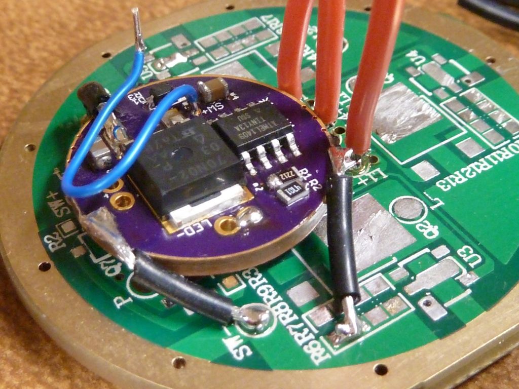
For the driver - here's a pic of the orginal mod (not now):

I simply replaced that piggyback'd driver with the new 85 based FET+1.

The usual thinking for decoupling is to have a smaller value capacitor millimeters away from the consumer and another larger value capacitor 10s of mm away. In this case the roles would be fulfilled by Czener and C1 respectively. The idea is to have a low inductance connection to the first capacitor. For this we need short or no tracks and a physically small capacitor.

D1 complicates things and we may inadvertently create some kind of charge pump. Will have to think about that one.

4 MHz should be easy…different fuses…#define F_CPU 4000000UL…and adjust _delay_loop_2 if you are using it. PWM will be half speed of course. And the clock will be outside factory calibration for the same reason as running the 13A at 4.8 MHz.

Looking at the photo there is potential for a ground loop. Test bringing only one ground wire to the driver and bring it to a point close to where the MCU takes its ground from (close to R2).