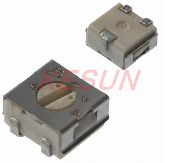
I was hoping for something closer to 25kohm…. I’ve never had to use a higher value than 22.1kohm, plus I have the other resistor pad in series bring it down a touch more. I’m worried 0-100kohm in one tiny pot is going to be a nightmare to tune…
Still better than soldering/unsoldering resistors till you get it right though.
I think this is what I have. Honestly I think it’ll fit under my springs, I’m just worried it’ll be too easy to bridge solder to the inside switch pins. I’m not worried about the outside pins because the case is neutral. I’ll do a board in about 4 hours.
My idea is to bridge the other resistor pad and have the full range to adjust (the bleeder resistor will determine the maximum brightness) , and the 100K is to be able to effectively switch the lighted tail off. I will see about the tunability. (I have not found logarithmic pots in this size yet, just lineair ones. Come to think of it, if logarithmic pots are used, the orientation of the pot does matter )
It would literally only take about 45seconds to move the trace to the other pot pin anyways. I just know it will be easier for me to remember right=bright
I still have not got my BLF A6 to work properly.
If I adjust mode to moon then switch it off I get sometimes a mode were the LED did not light up, so the switch is pressed but no light shines…
I used a 680ohm bleeder.
The diagonal measurement of 4.5mm square will be 1.414 times bigger or ~ 6.3 mm which would almost certainly touch the spring when compressed. Definitely need to know what the case metal is grounded to.
On the big one Djozz posted, It looks like it’s just a clip and not connected to anything else. On the smaller ones, I think the case is the same as the “slider” pin
Maybe, maybe not. Depends on the internals. I gotta think it’s likely metal for a reason until proven otherwise. Being a resistor it may only be there for absorbing heat. I would test it against the pins for continuity.
 )
)