Hi Tom,
An oscilloscope would really help here. Lacking that:
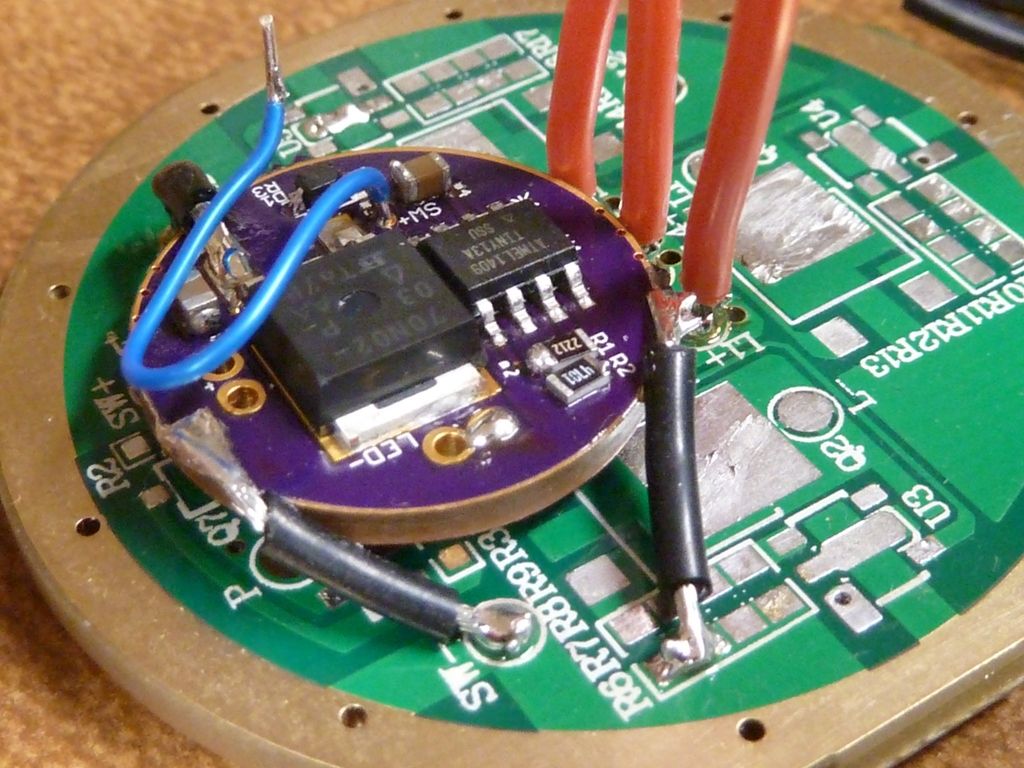
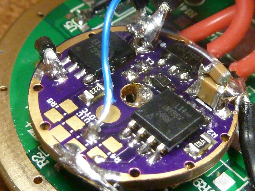
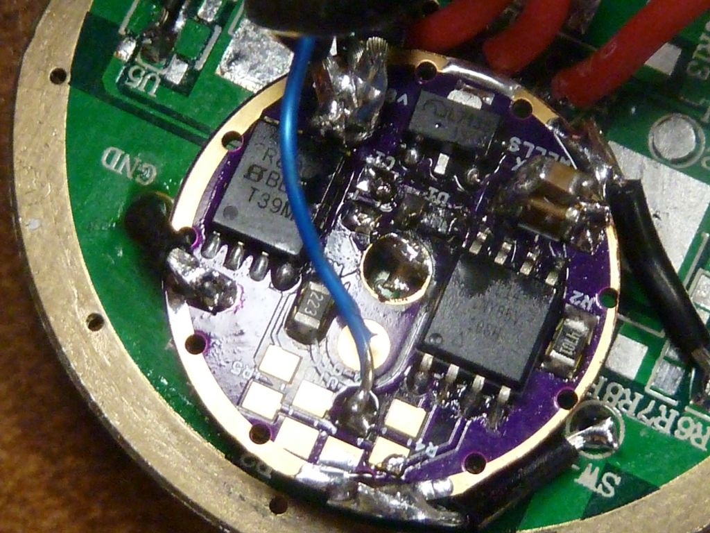
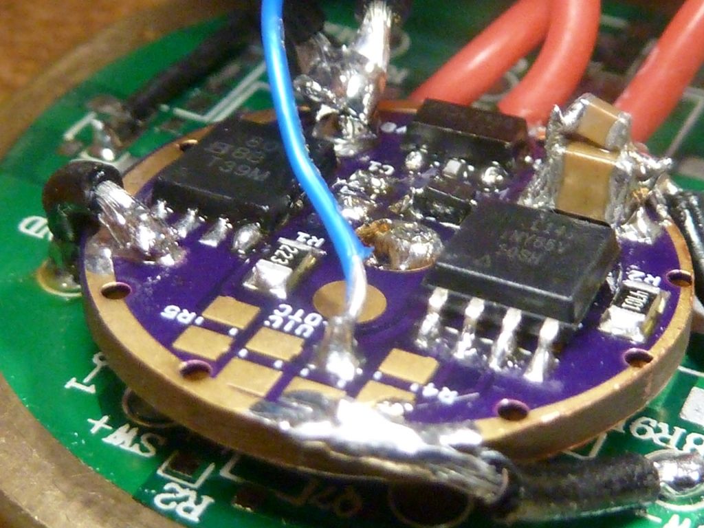
As with most drivers, the placement (and size) of the 10 uF is really not ideal for decoupling the Vcc of the MCU. Looking at the layout of the driver, the Zener diode pads seems to be a better location for a decoupling capacitor. Assuming you are not actually using a Zener, I would try installing a 0.1 to 1 uF on the pads intended for the Zener. Or temporarily add one directly on top of the MCU between pins 4 and 8, with short as possible wires/leads. Leave the 10 uF in place, or doubled up as you already did. You can also try to replace the Schottky with a 4.7-22 ohm resistor to isolate Vcc a little from the switching noise.
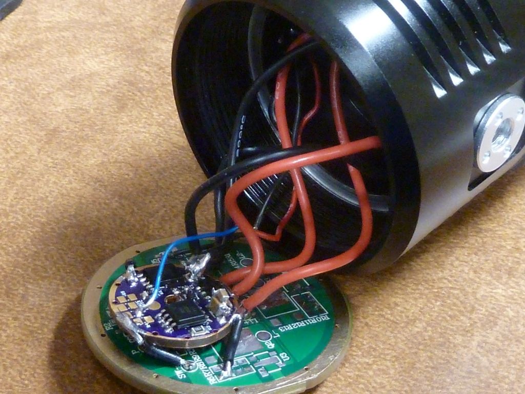
Another possibility is that you are getting excessive inductive kickback from the wiring. How long are the wires between the driver and the emitter(s)? Jumpers on the MCPCB? Any wiring involved between the cell and the driver?
Shorter wires would be easier to pulse. Keep the emitter wires close together (twisted) to minimize radiated noise and away from the MCU, if possible.
Also enable 1.8 V or 2.7 V brownout detection if not already done. At least then you could see the MCU reset on voltage dips, rather than freaking out.
Re. the timing of the 13A, apparently the oscillator calibration register boots up with the factory calibration value that applies to a clock speed of 9.6 MHz. If you want to have the advertised timer accuracy at 4.8 MHz, you have to manually overwrite the OSCCAL register during boot with the applicable factory calibration value (it is there, just not normally used).
 .
.