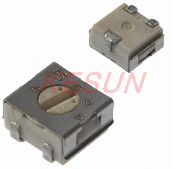
It is a bit bigger (4.5x4.5x2.55mm), but this Bourns 3314 type will fit the solder pads as well I think, and it is a bit more robust:
It is a bit bigger (4.5x4.5x2.55mm), but this Bourns 3314 type will fit the solder pads as well I think, and it is a bit more robust:
I still have not got my BLF A6 to work properly.
If I adjust mode to moon then switch it off I get sometimes a mode were the LED did not light up, so the switch is pressed but no light shines…
I used a 680ohm bleeder.
I do like that slotted type better than the “phillips” type.
I don’t think anything bigger will fit
The diagonal measurement of 4.5mm square will be 1.414 times bigger or ~ 6.3 mm which would almost certainly touch the spring when compressed. Definitely need to know what the case metal is grounded to.
On the big one Djozz posted, It looks like it’s just a clip and not connected to anything else. On the smaller ones, I think the case is the same as the “slider” pin
Maybe, maybe not. Depends on the internals. I gotta think it’s likely metal for a reason until proven otherwise. Being a resistor it may only be there for absorbing heat. I would test it against the pins for continuity.
This bigger footprint is causing me fits… Will the smaller footprint we originally were using still work? Just less selection in pots?
Yes but I haven’t found any POTs in that size
The Bourns 3302 series?
http://www.digikey.com/product-detail/en/3302W-3-103E/3302W-103ETR-ND/612823
2.75x2.2x1.05mm
Expensive tho if you don’t need to many due to shipping
I think the extra cost may be worth it for me though. I can’t find a good way to fit the bigger pot on the top.
Is that the footprint that you originally posted pyro?
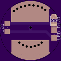
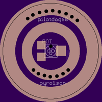
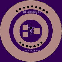
Alright, I was able to fit the bigger POT on the top side, and I think I fit the switch cleanly enough on the bottom side. It’s not as pretty as I wanted, but this time function came before form. Check it for errors please.
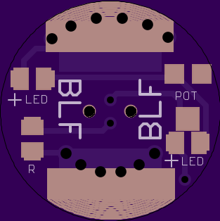


The listing I ordered my switches from is no longer active, but these look the same. To make the library part, I used the dimensions from this page, but rechecked most of them myself.
Between Pyro’s and my own boards, we’ll have about any option we want!
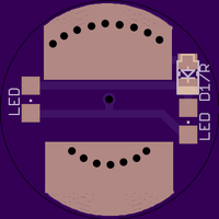
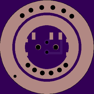
Looks good. How about a via for spring bypass between the two wide spread pins just kissing the spring ring?
I’m not sure if I understand. I think I would have to move a trace and even then the hole would be directly under the switch body.
Right, if you flip the switch around so the button is to the top then the via could go at the bottom(~5 o’clock). You would need to slightly alter the switch traces but I think it should work.
The via would be between the wide set pin pads and close to the spring ring with a generous trace but wouldn’t be under the switch at all.
I mean it would be directly under the clicky switch body… And I don’t really understand the purpose.?
It bypasses the spring. The vias are sufficient to carry the current through the board but springs are generally poor conductors and can overheat and lose their temper in high current lights like triples. The via allows even a smaller 22-24 gauge wire to dramatically improve output and protect the spring.