Nice!
I reflow driver boards on a hotplate btw, works perfect as well.
Nice!
I reflow driver boards on a hotplate btw, works perfect as well.
Right, so don’t set your pots to 0! :bigsmile:
There just isn’t anywhere to put another component that I can see. If you just want the on/off function, Rev2 and Rev3 have the resistor in series with the pot.
With a bleeder of 560 Ohm, and a battery of 4.2V, even without a led the current will be 7.5mA which is fine for those tiny leds. With the led in the circuit it will be less than that.
Good info Djozz.
I’m a bit absent-minded at the moment, so if someone could check my circuit that would be great.
This is just awesome!
Making a simple part that complicated can only being done by BLF :P.
Right, don’t drink and pot! :bigsmile:
Interesting progress with the switching, one can set between glow and nightlight mode.
Maybe we can drill the tailcap and allow access to the switch from outside in future versions. That would be cool.
Whenever I grab a light to show off to muggles, it’s usually my naked S8 and it’s usually in the daytime indoors, so I want the blue tailcap to be bright enough to stand out. The rest of the time, I want it more dim and functional. That was my inspiration.
Thanks pilotdog, using a via and means less solder wicks up the wire to stiffen it when you add the spring. Also means less likely hood of bridging in this case and placement is automatic.
Good to know, RBD. So is that a good size and placement? (although I don’t know how much I could change it anyways)
Placement is great. Via is big enough for awg18 though I think the insulation of silicon wire might be to thick in that size to clear the spring. Thoughts on that? I’ve only done solder wick bypasses so far so not sure of the ideal wire size but a .8 via would still allow up to awg22 and put solder mask between the via and the spring. The problem I’ve had is the spring requires more heat to wet and sharing the same pad means the wick takes up more solder than is wanted. A via takes less space than a pad and is easier to keep discrete. I appreciate the work that goes into this and I’m making an effort to consider how this board might be used by others besides myself and not just making more work for you. Thank you.
1.1mm is the drill diameter I used for the via, but I think that’s before it gets plated. They always end up smaller when I get them from Oshpark. I understand what you’re saying about wicking, but I don’t think I can do much to get around that. Even if the pad is small enough to have solder resist between it and the spring, it’ll still be connected by the copper underneath. I would just solder the wire in its hole, then tack the spring down in the two corners furthest from the wire to avoid the wicking as much as possible. I never solder the spring all the way around, just in 2 or 3 places.
PD and pyro you guys are awesome!
My first adventures with the transistor circuit, quick story because I need sleep now.
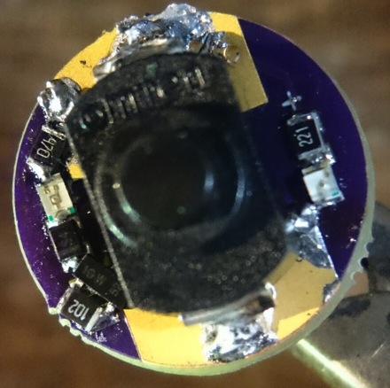
I used one of the older boards, cut some traces, scratched off some solder mask and got the circuit done.
Long story short, it does not work straight out of the box, I tried lots of other configurations and resistor values (the bleeder eats voltage so that has its influence on the working of the circuit), even refreshed my knowledge of NPN transistors for this (keep enough voltage over the base), I get red light (most of the times), I get blue light, but no switch-over at certain voltages. Too low resistor values even keep the driver MCU alive (LVP warning  ), etc. What does not help is that I have no electronics background.
A dedicated board would help the testing, but if it will work at all in the end, I don't know.
An explanation of how I think the circuit works: at voltages closer to full battery the green led (I used blue btw) lights up and that keeps enough voltage on (and thus current through) the transistor base that a free current flows from emitter to collector, thus bypassing the red led, that stays off. Below a certain voltage the green led drops out, the voltage between the transistor base and ground drops below 0.7V, the transistor stops conducting and the red led lights up. Anyone knows better than this??
Next round of fiddling some other time..
Are there no pots available which can be adjusted from the underside so that we could turn the pot through a small hole….?
Edit:
Trimmer rear adjustment…
http://www.mouser.de/ProductDetail/Murata-Electronics/PVZ3R203C01R00/?qs=sGAEpiMZZMukHu%252bjC5l7YV%252byaHoSF4AhtvSsUE%252bGmnw%3D
That was what I had in mind a few posts back… would be great for final adjustment.
It Would also make the Second Trimmer and the switch obsolet…
I disagree. I feel adjusting such a small pot with such a wide range of resistance is going to be very very touchy. And you won’t be able to see the led’s when you’re adjusting it. I’d rather have preset options that I’ve already dialed in to where I want them.
That’s just my opinion, but it sounds like the boards pyro already made are perfect for your desires.
you can also dial in your preference and mark it with a permanent marker so you could simply “switch” between preferences once you have found them. Depending on the position it might be able to write down some “clock like labels” so you can just use resistance number 3 and 8.
Also I would simply wire it up while adjusting it, crocodile clips are our friends;)
But maybe I am underestimating how close high and low brightness are…
The benefit would be that no parts would be in the battery compartment. And that the hole could be not in the center where the spring with bypass is a big obstacle.
But anyway it seems that the rear adjustement trimmers are rare and big…
I thought trim pots didn’t like being moved much. More of a set it and leave it thing.
Just an FYI. Looking at a mini omten there is a five pin locator on the bottom. Four .55 mm plastic pins in a 2.7mm square(2.9-3.1mm outside dimensions) with one in the enter. Could be easily cut off or pattern incorporated into boards.