Attiny25/45/85 FW Development Thread

Ohh- sure. Haven't touched it in a long time, but it works well - but would benefit from the same exact bug fix. Not all drivers had the flicker though.

This link google drive folder has the version for FET+1, and the older version with a single output - both 13A versions.

Update: in my test light, Supfire M2-Z, I've been using the wight 22mm FET+1 board with an 85. I experienced flaky operation on occasion all along I believe - blinks, sometimes it even locks up. I added a 0.1 uF cap on the zener pad and seems like the flaky intermittent problems went away. So, I left the stock 10 uF on the C1 pad. I believe this light and the SupFire M6 were the only two I've used this driver board on, at least with 85's, and both had intermittent problems in the stock C1 setup - caps on the zener pad seem to solve it.

^

Thanks. I think you had a solid 85 version that you published that was still under (or very close) to 1K. Not sure what all you had done to it. I'll try to port it back and fix the issue you mentioned above. If that doesn't work I can go to the 13a version you mention above.

Regarding the newest FW you released: I didn't finish my SRK to test your new FW last night. I should finish it today and then I will report back.

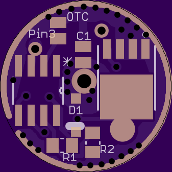
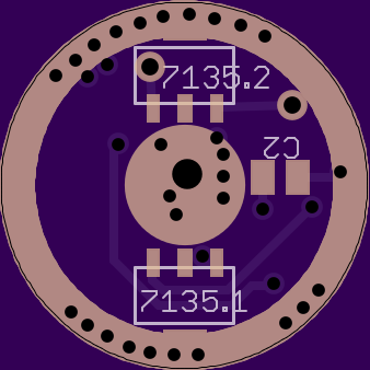
I built up this light: tinywind ultrafire UF-T18, with a 219C on a 16mm Noctigon, using Richard's driver board: https://oshpark.com/shared_projects/acdEm3rR he posted here in post #163. It works great on a laptop pull cell @3.2V, works intermittently on a Panasonic 2800 mAh @4.15v, and doesn't work well at all on a SANYO GA @4.2v.

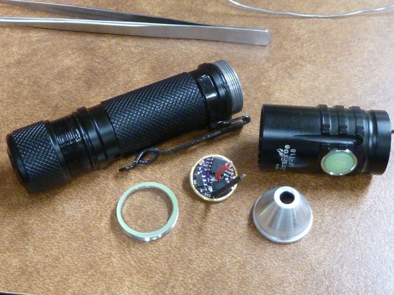
Quick review of UF-T18: nice compact 18650 e-switch tube light, it's a real UltraFire (driver is branded UltraFire), real SS retaining ring in the bezel, easy thread lock-out on the tailcap, body mounted side switch with 3 wires: grnd, switch, and bonus: RED LED in the switch! But the side switch is not so good - lot of force needed for the thumb, works ok on the tip of the index, or can use your finger nail, but don't think the rubber would last long on finger nail use. Bottom line: the switch is a killer disappointment without a fix, but I am not a side switch modder...

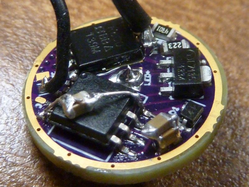
The problems appear to be the same issue I had in the other lights with the 22mm wight FET+1 driver, but now I don't have any zener pad available after the diode. I'm sure the problems have something to do with the low Vf, high amps of the 219C (5000K from Richard). I'll try piggybacking a 0.1 uF on the C1 cap, and see how it works. If it fixes the problem well, this may be the ultimate solution going forward for all 25/45/85 builds.

Richard's board design is pretty good, but using a SIR800DP, there is very little pad space to solder on the LED- wire to. A 22 AWG wire barely has enough to grab on to. I don't think a 20 or 18 AWG wire would be an option - no space, too tight against the resistors. I also have all 3 sizes of PD's DoubelDown drivers (https://budgetlightforum.com/t/-/35301, also post #202 here) - the LED- pad looks better, but haven't tried a board out yet.

Update: the piggyback 0.1 uF helped - tried a Pana PF and seems to work 100% where before it was failing, but on a SANYO GA, strobes don't work, unexpected blinks, etc. - same old problems. Maybe try another stacked 1 uF so I'd have a 10, 1 and 0.1 in the stack?

Boy, dunno... This light is a PIA to be experimenting on - desoldering wires from a sunken LED, 3 pt. soldering of the driver to the brass pill edges.. yuk . No time now - gotta assemble some furniture - my wife went shopping at IKEA...

I am a little surprised that the 0.1 uF made any difference. It really should be right up against the MCU to fulfill its purpose. It is standard practice to have these 0.1 uF decoupling capacitors VERY close to the MCU. We are fortunate not to have more issues with the layout of typical drivers.

In this case best I can recommend is to have a 0.1 uF straddle the MCU. Glue it diagonally to the top of the MCU and run leads/jumpers directly to pins 4 and 8. Pain in the butt for programming though.

Next best option is leave out D1, at the risk of frying the MCU when reversing the cell by accident. Re-use its pads to fit a bigger capacitor.

Did you try running at 4 MHz? That should also give you more room before brownout.

Sorry, really dunno the specifics or converting to 4 Mhz - suspect there'd be some testing. I'm gonna try the piggyback 0.1 cap now. Dunno what glue to use (?) - might just have to suspend it. Thought super glues were NG for this stuff - not sure... Again, I'm not so used to this experimentation and not set up well for it.

Sorry I didn't get any testing in yet. This damn Kung is kicking my arse. One problem after another every time I work on it.

No prob - ImA4Wheelr

DEL - that dang little cap across the MCU worked !! SmileSmile At least so far. Before on a SANYO GA strobe didn't work at all, and now it's working flawlessly so far. Accept the dang thing gets so hot so quick. I'm using 22 AWG LED wires, added spring bypass's on the tail spring and in a tiny driver spring I added - original driver had no spring at all.

A pic of the UF-T18:

Here's the driver in it's final/current version:

Here's the driver spring w/bypass (used a 26 mm wire in there - very short):

At the tail, I got 6.3A with the GA cell - crazy #'s, but with the 219C 5000K, I'm getting about 1,000 lumens out.

Note: Both added caps above are 0.1's, but, one is 50v rated (square on the MCU), and the thinner one must be a lower V rating, but not sure what it is.

I'm thinking we need a board design with a 0806 pad for a cap that gets + after the diode, close to the Vcc MCU pin #8, and either goes to a strong grnd, or gets to a ground close to the grnd MCU pin #4.

I dunno how it would fit on a 17mm board with the wide pads for a 45/85, but, thinking this will be the ultimate solution - using a 0.1 uF cap, or thereabouts.

I also would love to have pin #3, the spare I/O pin wired to a pad for a secondary switch, or ON/OFF LED output. I think the MCU pin #3 can work for that.

Any takers? PD68? RMM? pyro1son? Smile

FWIW, I finally merged in Tom E’s eswBrOutCfg project.

Also, I’m still eager to hear about further developments on the issues you see on strobes and other sudden flashes. The cap over the MCU is interesting; I wonder if it could be placed somewhere directly on the board or if perhaps some other solution might work better.

Now I’m really confused. I think I’ve dropped the ball on this topic…

Wasn’t the conclusion that the cap should get + before the diode? Or are you considering one before and another after? Don’t most of the drivers have the cap + after the diode?

Leave it with me :wink:
10uf and 1uf caps?

If space was an issue, the board could use the SSU footprint and the cap be placed under the MCU. It would require the SU MCU package to be used and the pins to be bent in. When this is done, the MCU sits high enough to clear small 0805 caps underneath. Bent legs really make program clipping much easier.

Mike - yes. The large cap should remain before the diode, small cap after, at least that's what it's looking like. Think it gives us best of both. The test light continues to run smoothly. I got 3 lights now that had the problems and fixed now, all slightly different in cap values and placement, but all have a high value and low value cap, and the low value is after the diode.

The last driver, RMM's, is using a 0.1 uF cap, not 1.0 - DEL recommended the 0.1, though might not make much of a difference (I think).

Edit: that may be a viable option bout the bent pins technique. I am a bit concerned though bout the soldering of the MCU pins - certainly not as robust as when they lay flat on the pads, normally. I've done a few though and plan on doing more, and seems to be holding up well, but usually have to touch up a pin or 2 by hand after reflowing.

I vote for under the MCU.
It can even be on the opposite side of the PCB, but that would spoil the ‘single-sided’ feature. Vias also decrease decoupling performance somewhat.

The go-to size for local decoupling is 0.1 uF, but I think 1 uF will be fine as well in this case.
The tracks connecting pins 1 and 8 to this cap should be as short as possible and around 50 mils wide.

Atmel’s recommended decoupling is more concerned with noise emission from the MCU, but describes the basics well.

Atmel also recommends a series ferrite bead, this is not that applicable to our single supply MCU’s.

Pages 3 and 4:


I’ve made a start and added a few extra features very difficult to get everything to fit.
Pin 3 has a 0.8mm via that leads to a 7135 that can be populated if wanted or the via can be used as switch in ect…
The pads to the right of the MCU are the extra cap. It could be moved to the opposite side later.
Don’t think I will be able to get the 85v foot print, but I’ll work on it more later.

Will this still be compatible with chinese backyard production?
Remember the soldering job on the BLF A6 drivers…

DEL could answer this better, but I'd say probably not. This is more or less for us hackers , but, the chinese changed the BLF A6 driver anyway, so they did not 100% duplicate the wight FET+1 driver we started with. The soldering problems were not a design issue - it was a manufacturing/production/QC issue - sloppy and rushed basically, from the looks of it.

I work for a manufacturing company, and we insist our PCB suppliers test the boards before shipped to us. We will design/engineer/produce test fixtures for them to use in order to achieve as close to 0% DOA failure rate as possible. This is one way of doing QC - you want this done as close to the source as possible.

Sorry to say the way our group buys are done here are far from ideal in time and cost. This whole cycle of sample testing in the US is very inefficient and wasteful, but not much other choices unfortunately...

Sorting the layout, but never going to get the SU footprint on with everything else.

Let me verify the clearance under an 85 with bent pins tonight. I'm pretty sure that there is height for a 0805 1uF, but I haven't tested that idea yet.

Think it will depend on the voltage rating as well - higher the voltage, bigger the part. Think we use 16v rated caps in general. I believe it helps having a higher rating - not sure.