Think you really need some pad space for LED-, at least with the SIR800DP FET - there's nothing on the FET there to solder to. That was my issue with Richard's board.
I’ve moved the FET away from the edge and the 2nd CAP from under the MCU as I just don’t like the Idea. I would rather just put both caps on the bottom of the board.
I'm liking it  . Nice to have a pin #3 pad.This last one is still with a 13A footprint, I believe. It's still a lot to squeeze in.
I'm think'n we'll need it both ways - one design with the full 45/85 footprint, and one with the 13A/25 size. I'm thinking Richard will be working on a design as well.
It’s definitely a squeeze with the 85 footprint
Nice looking board.
Thanks for the info on the SiR800DP guys. I haven't been keeping up on FET's.
Should be noted - this happened to me twice already. The 380 7135's seem to want 5 as a PWM value at a minimum (moon mode) - not sure if this has to do with the faster PWM rate of PHASE correct mode on the 25/45/85's when run at 8 Mhz.
So what I'm using now is using 3 for 350 7135's and 5 for 380 7135's as a standard practice. The 5 on a 380 may even be lower output than a 3 for a 350.
Also, I made a change in the firmware that was annoying me. For going into lock-out with the 2 clicks, then click/hold, I made the hold time shorter so you don't have to see that annoying strobe. So basically instead of strobe for about one second, you get the 4 short blinks - much more pleasing, easier to enter and confirm you are in lock-out. I checked the manual and didn't see an impact there - I didn't get too specific on hold time in the manual.
Update, more changes to the firmware:
Couple more things that kind of bugged me:
- losing your place in the configuration settings. With 5 settings, hard sometimes to track if your are on setting #3 (mode ordering) or #4 (mode memory) for example. So, I now do 2 fast blinks, then blink the setting # when entering a configuration setting. When you get to 5 of course, it takes some time to do 5 blinks, but hoping it's easier to track now.
- No way to completely bail out of configuration mode - you can skip to the next setting by click/hold, but still takes a while. So, I added a long hold option to bail out completely. So in configuration mode, a hold of about 1/2 sec skips to next, while a hold of 1.1 secs bails out, signaled by 5 fast blinks. I increased the config mode exit blinks from 3 to 5, since they blink faster now.
Not yet posted... Will be doing more testing... Once again, the SupFire M2-Z light is working great for re-programming/testing . Thanks Richard!
Hi all,
Just want to start by saying thanks to everyone putting time in on this project.
I have an idea about making some extra room for component placement on this driver. I dont know anything about running the electrical traces so if this sounds dumb please forgive.
What if the foot print for the larger micro 45/85 and the FED were put on the bottom ( the spring side) and all of the other components were put on the top. The work around for loosing the spring pad on the bottom could be mechanical.
The battery + could be a large via in the center (like in some of the above desings) that we could either just solder a rivet into or use a machined part with a larger top that a spring could be soldered to.
Like this.

I would think the top components could then be reflowed on and the bottom 2 could be hand soldered easily. Plus if only the rivet was used for the + contact the micro could be reflashed without unsoldering the driver from the pill.
Copper rivets are cheap too, a box of like 250 is ten bucks.
My 2 cents....
Interesting... You lose a little clearance in the battery tube, that's bout it. Not sure bout the rivet parts - best metal, etc. It gets away from the single sided driver, but at least we'd have room. I do a lot of piggyback'ed drivers still, and for those, the parts and spring would not be necessary anyway.
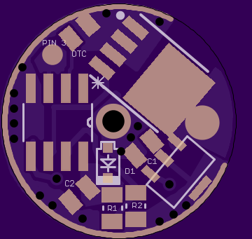
If you’re going to have components on both sides and want as much space as possible, just do this:

Those copper wires are solid and clear the MCU, at least on the drivers I’ve built with this method. It maybe a bit more work than your solution but by centering the MCU I not only have more space for components around it, I can also flash it without ripping apart the entire light.
The driver in the photo is 23mm but I’ve designed and built 17mm drivers this way, works like a charm as long as the cells are button top or have solder blobs on them. On some lights it might be a tight fit, but I haven’t had size issues with any of mine yet.
Narsil is here - click on the sword to get the manual:
Get Narsil firmware here, folder link that includes PDF of the manual: drive.google.com - ATtiny254585Support
Taking up the handle-shard of Narsil after his father's defeat, Isildur cut the One Ring from Sauron's hand, defeating him.
Very nice, Tom :)
I haven't used the latest version yet, but will be putting it on the next '85 build I do.
Thanks again for making this available to everyone. :beer: :beer:
It's the same firmware renamed - little catchier and simpler . Current size is about 3600 bytes. Latest updates:
Three changes, minor updates to the manual:
make lock-out easier by shortening the hold time which eliminates activation of strobe. It makes it easier to confirm if lock-out is set, because if strobe does activate, you know lock-out is not set
change the blinks for entering a setting configuration mode: it now blinks quickly twice, followed by slow blinks of 1 to 5 (1 for first setting, 5 for the 5th setting). It makes config mode slower but easier to track what setting you are in
add a long hold to exit configuration mode. A short hold will skip to the next setting, but if you continue to hold a little longer, it will exit altogether, indicated by 5 quick blinks
I don't know if any of you watch NCIS, but if you do I think you'll get the reference:
NCIS - McGee the Elf Lord - YouTube
I nominate Tom E. as BLF's Elf Lord. 
Very cool and very generous of you to share your FW Tom E. Looking forward to trying it out. I've been struggling to get in mod time for some time now. I hope to try it soon.
Thanks  . For Richard: go kiss an orc...
  "The time of the Elves... is over"
Might just be me but how to change modes when on?
Lets say, its in med for over 1.2 sec (its locked-in), how to go to the next mode?
Do you have to click and hold to cancel the lock-in and then click to switch modes?
Think yes, you are correct. Since the 1-click turns it OFF, you can click/hold to go to previous mode, then click to go the next, click->next, etc.
It's all a matter of priority - I chose to make 1-click OFF the priority, but I believe Werner originally had it working where changing modes was priority. You can change this behavior, if you like, and have it work without the mode lock-in feature - change the following from 1 to 0, at line #296 in Narsil.c (I think this should work - might not have tried it though...):
volatile byte byLockOutEnable = 1; // button lock-out feature is enabled +1
There has been a lot of work on this thread experimenting with bypass capacitors, but I did not see anything done with FET selection. Perhaps a FET with better dynamic switching parameters would alleviate most of these issues.
It looks like Mitko has gotten outstanding results on a FET he found. To me, the packaging looks like a SIR800DP, but I can't find it anywhere around.
Post #615 here: https://budgetlightforum.com/t/-/30080, data sheet: https://store.comet.bg/download-file.php?id=7648
Talked about here as well: https://budgetlightforum.com/t/-/35815
If anyone can find it, please post. Mitko was seeing 5-8% bumps on amps, and he mentioned they were even pretty cheap. Dunno about any side effects though.
For those who can shed some light on it, please check out the data sheet. I'm thinking there may be an equivalent sold under another name/part # somewhere.
The big deal for us is the amount of gate charge at a given gate voltage. Usually, the lower RDS on FETs have a higher gate charge. We are switching relatively slow (<20 KHz) but we are are also asking a lot more from the MCU than it was designed to do. We get away with it most of the time in the name of compactness and simplicity, but it would be best if there was a gate driver, even a makeshift one, that drove the FET gate. I have experimented a bit with this, and while it does work great I don't think that it is necessary to add the extra cost, however small, and complexity to these drivers.
Since we aren't really pushing the thermal dissipation limits on these FETs in the partial duty cycle modes, I think that adding a gate resistor back into the mix may be the easiest solution. This will ease the load on the MCU and we don't really care if the FET spends a few more microseconds in the linear region with the loads we are switching with them.