Thanks Mitko ![]()
Can't locate those MOSFET's anywhere. The manufacturer, APEC, doesn't seem to be popular. Can't find them on Mouser or DigiKey.
Hm… strange, i posted those cause in Europe they are cheap( 52cents with our huge taxes) and good, was thining they would be an easy find in the US
At least we have something that cant be found in US! ![]()
P.S

I am on a night swifth making some of those atm btw, hunters got pretty active lately, maybe cause of the Xmass
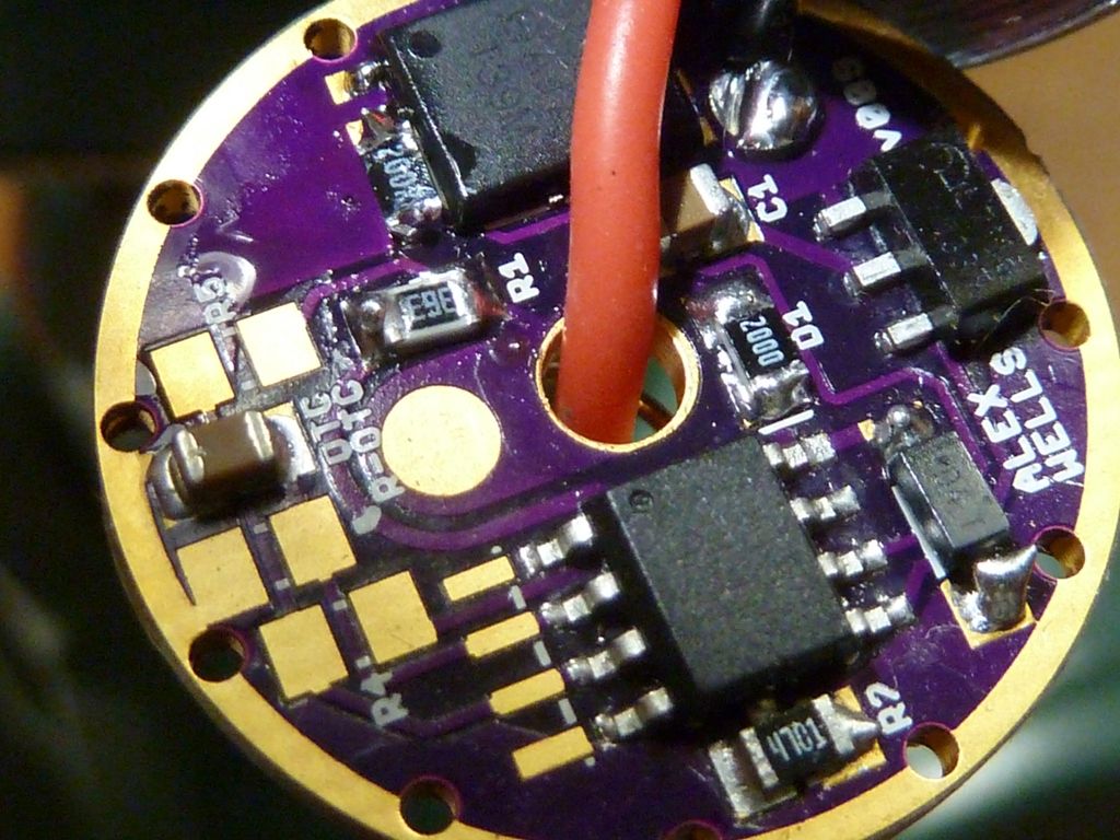
Tom i have a question, do you also like me recieve every time those with a different minus contact area thickness?
Those on the photo got thick minus contact rings, sometimes my order comes with thin ones, sometimes even the contact circle is covered completely and i have to rework them
Mitko is this the version of the board your using?
Boy, I'm confused... I'm only using FET+1 drivers - wights v009 version, same one that the BLF A6 driver was based on. I really love having the single 7135 to have very efficient low modes.
Think what you (VOB) and Mitko have are FET only boards - I never ordered that specific board - I used to use the ones in the OP though. OSHPark support told me they've had these weird masking problems with wight's boards (a few) intermittently - they dunno what's causing it, couldn't explain it. I got a batch in once with pads covered, asked them, and they rushed out a new set free of charge, even though I could scrape off the contacts and salvage the bad ones -- OSHPark has great support, try them.
For the masking of the ground (I think you mean the outer ring?), don't think I've seen that specifically, accept the set of boards that came in that one time completely covered, but it wasn't this board.
Actualy that masking isnt that big issue….just asking, OSHPARK are quite good to me anyway
Yeah i am using mostly v44 cause most of my stuff simply dont need fet+1 drivers, plus i `ve discovered something interesting: some XPG2 emitters dont like FET+1 driver, for instance S2 1A from FT- i have absolutely no idea why
Hunters flashlights usualy dont have that low mode ![]() 700ma, max, battery check, things like that…ppl got annoyed with too many modes
700ma, max, battery check, things like that…ppl got annoyed with too many modes
But ofc i am using Fet +1 too, just not that often, like 6-7 monthly
Ordered Attiny 85s btw, have to try our your new firmaware
Thanks for developing it TOm, greatly appreciated
Thanks  . Ahh - true, good point bout the simpler mode sets. For tail power switch lights, the high mode count and advanced features can be frustrating - for me it's more awkward to deal with than a side switch., though I'd still like to have 2 e-switch's.
Can't recall - was there any advantage to this PCB alternate layout vs. the one in the OP?
VOB - sorry, what exactly is the 1S and 2S driver, and what is a Cznr pad? Think something to a with a cap and/or zener - not sure. Couldn't answer your question cause couldn't understand it.
Thanks Tom, I will clarify. By 1S and 2S I mean can the board be configured to use 1 cell or 2. On my drivers and on RMMs there are 2 separate places to put the 10uf cap. One place is used if you make the driver for a single cell ( C1). The other place is for putting the 10uf cap if the zener diode is use for the 2S board (CZNR).
On this board I see only one place show for the 10uf cap so I am wandering if the board works in both configurations or only when used with a zener diode.
Ok - think everything is there - the C1 pad, the D1 pad to the right of C1 (unmarked though, but indicated by the arrow), then the zener pad to the right of that. Should be the same # of pads. I don't know off hand how to assemble a zener driver (for 2S). Can't find a pic...
Oops, this is one I did for a Roche LS01:
So the 200 ohm resistor goes on D1, and the cap stays where it normally is on C1, and the zener of course on the zener pad. At least this is how I did it, what I thought...
The more I look at the v043 design/layout, the more I like it. Simple but everything is there. Main problem I have is pin #3 and pin #5 are not wired, and would like to use them for LED indicators, so even if they went to a small pad, it would be great.
Update:
Ok - now I understand... You are talking about Richard's Mtn-17DD driver v1.11 here: http://www.mtnelectronics.com/index.php?route=product/product&path=25_122&product_id=272
That board has a CZNR pad that the 10 uF cap is moved to when in the zener (2S) configuration. Interesting, so he moves the cap after the resistor...... Hhmm... I'm thinking Richard had a good reason for moving the cap so it's after the 200 ohm resistor, and not before. If it's before, I'm thinking it's getting 8V from the 2 cells, but if it's after, it's at 4V, like the MCU... Oh boy.
Dunno - Richard, or someone more knowledgeable needs to address this.
For the zener mod. configurations it is best to have the capacitor after the resistor and next to the zener diode. If you don't, you will get a voltage blip on a lot of startup events that will wig out the MCU. Wight acknowledged that this is a potential issue in the OP, and I found out with my very first revision boards that it doesn't work reliably unless you change the circuit, so in my second revision boards I added the second pad so that you could zener mod without having to stack anything.
The only reason we don't always run the capacitor closer to the MCU is because driving the FET causes an MCU over voltage boost if you have the capacitor after the diode---the inductance from charging the gate charges the capacitor to 6V+ and it has nowhere to go with the diode blocking the backwards flow. It was comfychair who first scoped this out, and I have since verified his results.
Good to know Richard, thanks! I couldn't find it mentioned in the OP though. So, my wight driver in the Roche LS01 pictured in post #627 has it wrong because the cap is still on the C1 pad, before the resistor, but wight's boards don't have the extra pad your driver has. So probably best thing to do on his boards is stack the cap with the zener?
The LS01 seems to work fine, but probably because it happens to be tolerating the voltage blip?
It really depends on the light and components. I built some that worked, then some wouldn't work right. Alex then tried some and found pretty much the same thing. Moving the components closer together solved most, but not all, issues. Stacking or changing the layout will work 100% of the time, which is why I went that route.
1. It’s mentioned all the way at the top of the OP - maybe it’s not prominent enough?
2. Yes, for any version before v030 stacking is definitely recommended for Zener builds.
The interesting thing here is that as far as I know, Nanjg drivers always worked without moving the cap! That means that the a PCB layout change can at least allow the circuit to work. Bad things could still be happening under the hood of course, but that’s the case with many of the things we do. If I’ve scoped this to see what’s happening I’ve certainly forgotten the results. I’m going to trust RMM on it - a high-voltage blip is causing the MCU to wig out before the zener can get the voltage under control. In v024 (the most popular version I think?) the cap was a looong way away from the MCU. That was always a bad thing to do - as I recall I knew that when I did it. As I said above - we do lots of bad things with these drivers. It didn’t turn into a problem for single-cell stuff, but for the Zener builds it was a problem.
That cap placement issue was what v030 and v044 were supposed to fix. In both versions I moved the cap much closer. I do very few builds and only a minimum amount of testing. Did those versions not fix the issue?
(or maybe nobody ever tested them because I didn’t document them well in the OP?)
WIGHT IS IN THE HOUSE AGAIN!!!
OMG man, i we missed you sooo much! Belcome back! WIll you stay for good? I realy do hope so
I use mainly v44 atm, builded like 20 of those drivers zener modded and yet i havent met that issue
Thanks folks! I’m here for the moment and we’ll have to be satisfied with that for now! ![]() I’m definitely glad to see you all and post a little.
I’m definitely glad to see you all and post a little.
@Mitko - thanks for the info. At the time I wrapped up v044 I felt pretty good about it, but without testing there was no way for me to know! It appears that you’ve done the hard work for me. ![]()
Can somwone explain what these are and what differentiates them from what they’re replacing?
WELCOME BACK WIGHT! Maybe you already know this, but you invented the greatest flashlight driver since the 7135 based driver, and this one is a land slide better!! Thank you..
borked,
The main advantage of this driver is that there is basically no real limit to the current on this driver.
For example many budget lights come with a Nanjg 105C driver you may have seen similar to this.
http://asflashlights.com/en/-diy-parts/34-3000ma-led-driver-board-custom-modes.html
Those drivers are linear, but they have maximum output based on how many of those 3 legged chips are on the board. This one has a 3000ma.
Replacing that board with one of wights FET drivers would allow you to drive the LED much harder. Say for example an XM-L2 emitter driven by an IMR 18650. With the old driver 3000ma is all you will ever get. But since the FET has not current limiter your drive current will be based on the VF of your emitter. Typically with that set up you can expect roughly around 4 amps or so with a U4 1C emitter.
Thanks vob!
Just for the record, I didn’t invent this driver and neither did anyone else on BLF. This driver is merely an evolution/re-imagining of the ones worked on by the original BLF17DD crew. That driver was basically an improved copy of the Chinese “East-092” driver made with the goals of higher current and Nanjg-105c firmware compatibility. With that said, I think it was a big improvement.
At some point I need to revamp the OP. I reserved a post under it, so there’s a place to move the old content… the actual OP needs to reflect the current state of things better: advice on using a larger C1 for high-power builds, using v044 for Zener builds, etc. It’s probably time for v024 to come out of the OP as well. It’s probably my favorite in terms of looks, so it pains me a bit to relegate it to the “post #2 reserved / old content” area.
Time for me to build some drivers!!!
I just need some more info….
Would the v024 pcb work ?
What capacitor should i choose for C1 and what diode for D1?
I’m not going to build the “zener version”