Go to an Art supply store and ask for a “Mars” eraser. These are very soft and ‘grabby’ on glass, much better than the usual kind.
Phil
Go to an Art supply store and ask for a “Mars” eraser. These are very soft and ‘grabby’ on glass, much better than the usual kind.
Phil
If the light won’t turn off it’s probably due to the little nub in the center of the rubber boot being too long. You can click the light on, but the nub won’t let it come back out far enough to disengage.
Take the retaining ring out of the tail cap, pull out the switch board and the boot/spacer assembly and try them outside the light to see if that’s the issue. Easy enough to trim a slice off this nub, just don’t get carried away or the boot actuation will be mushy. The rubber boot should sit on top of the switch cleanly, not be held up above it. Cut off the nub as much as it’s being held high. This might not make sense reading it, but if you’re holding the switch in your hand and see it, you’ll understand. Just remember that the piece that looks like a washer is a spacer, the switch sits against this with the switch post going through the middle. So the boot should sit flat on the washer.
This is really easy, no soldering involved. Simply use tweezers or needle nose pliers to unscrew the brass retaining ring, then pull the parts out or push the rubber boot through with your finger from back to front.
1dash1, one thing there that’s not accurate… “later models had this flaw corrected by using a circular die and a circular centering ring”
They use a circular centering ring hole that completely clears the square die substrate, the die is still square. The only circular die in this industry is the Luminous SBT-70, SBT-140. The SBT-70 is discontinued and the SBT-140 cost’s ~$100 for the emitter.
Just wanted to avoid confusion. The reason the dome get’s stripped is multi-fold. As has been said, if it’s hot the dome comes off fairly easy. When the bezel is loosened, the downward pressure is released and the reflector can float, allowing the centering ring to rise and not stay mated square hole to square die substrate, thus hitting the hot silicone dome and bumping it off. This is usually done with the light held sideways while loosening the die, but not always. Part of the problem is that the plastic centering ring is not a snug fit on the square substrate, or it’s still hot and soft from our over-clocking the emitter. (Remember, the emitter has a 3A max rating and we’re taking it to 5A and over, over-clocking produces much more heat)
Primarily, all it takes is paying attention and some tender loving care. We have members here that simply will not open a light, we have other’s that insist on cracking it open right off the top, allowing humidity and dust to get in (and oftimes fingerprints). Should be fairly obvious that the light really shouldn’t be opened in other than ideal situations, at the bench, in a more controlled environment. This especially holds true to custom lights. Many times it’s very difficult to get a de-domed emitter sitting perfectly in the reflector for maximum throw. Loosening the bezel could kill an hours worth of tweaking and make the light never really work right again.
Also, if the light is on when the bezel is loosened, the driver wires can lift the mcpcb off the emitter shelf, eliminating the heat sink. The emitter will overheat quickly, smoke, and die. AND, if the dome is bumped off, the reflector can easily damage bond wires that are now exposed.
Caveat Emptor!
The XP-L is really succeptible to damage because of it’s construction. Because it uses the XM-L2 die on a XP-G2 substrate the dome is all the way out to the edges of the substrate, so bumping it with the centering ring or reflector is probably more likely to cause damage…

This is from CRX’s thread here on emitters. Sorry it’s so big, it’s a single picture of the build of a lot of emitters, can’t trim it down to the specific XP-L or XP-L HI. But seeing some of these other’s gives a great perspective to what we’re dealing with in our lights.
Ton’s of great information in his thread!
A truly round die in a square hole, the SBT-70 in a Mirella reflector modified to fit this emitter and the Eagle Eye X6. ![]()
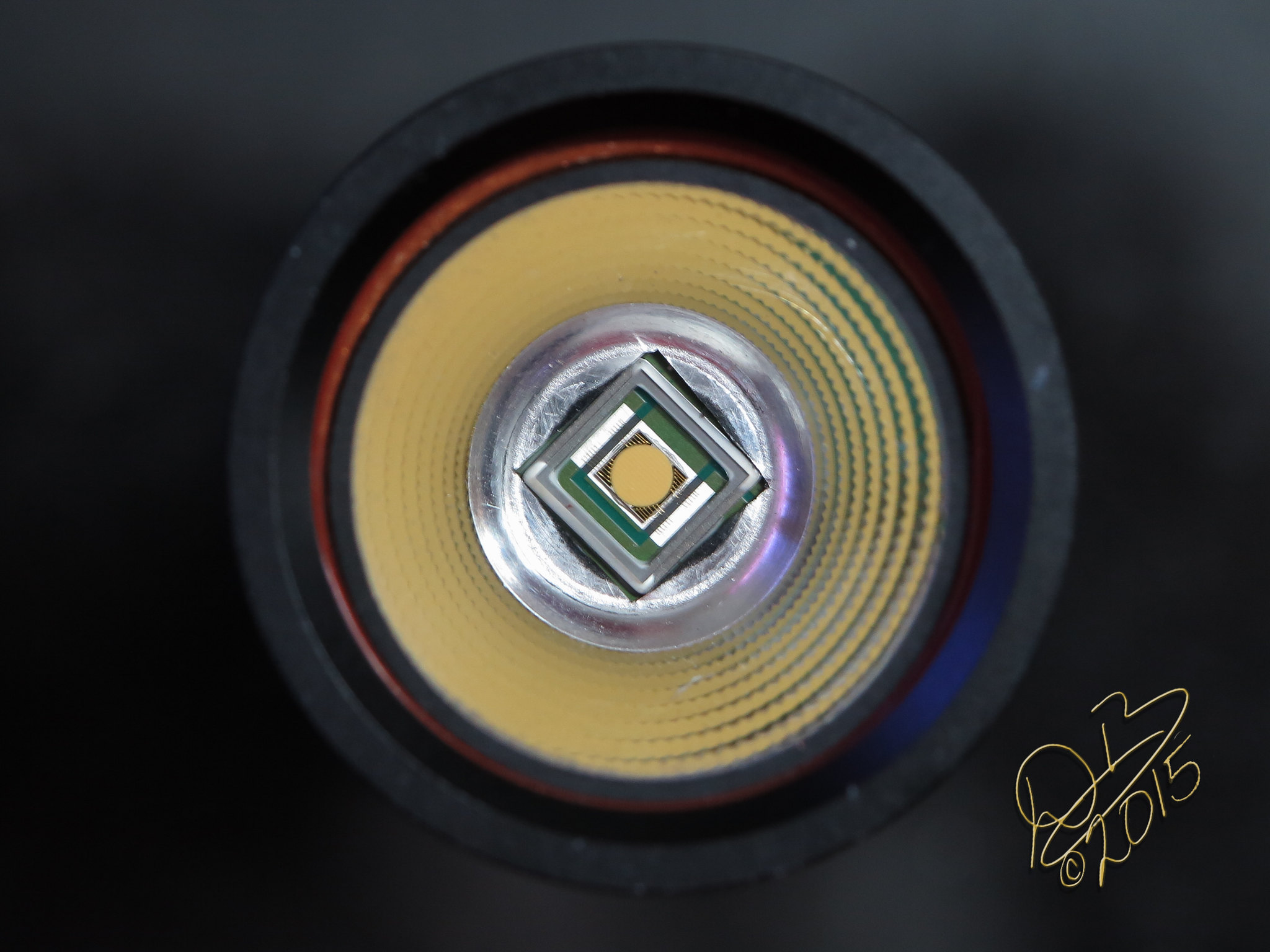
Don’t see the dome? It doesn’t have one, they put an AR coated glass window on a metal frame for protection. The silvery edges are the metal frame, the glass lens is glued onto this frame which is likewise glued to the substrate. I like pulling them off, leaving the bare round die exposed with it’s bridgework of bond wires. (I have also slipped and crashed that bridgework, killing a $70 emitter!)
+1, even if it works it can be too sensitive or not tail stand if the rubber is too tall.
Dale, Thank you Very Much for the SUPERB explanation. 
And for your Always Valuable posts. 
Could not have explained that any better. Thanks D.B.!
![]() He’s gonna hit that 10k mark faster than we originally thought!
He’s gonna hit that 10k mark faster than we originally thought!
thanks for the reply. i tried this, but it did not solve my problem. i cut a very small amount from the nub, which did not work. i proceeded to cut small sections off and testing, but it never worked. i eventually ended up with the boot actuation becoming mushy like you mentioned. still nothing. below is a picture of the trimmed nub next to the untrimmed nub from my extra boot.

Does the switch work properly (click in and out) when it’s out of the light?
yes, it appears to. i have a second light that works perfectly, so i took the switch out to compare. they both look and sound the same.
i should add that every once it a while it does turn off. however, i’ll leave it sitting on a desk and it’ll randomly come back on. blinded me a few times, haha.
I have my A6 driver that I ordered from Banggood on December 3rd. It looks nice.
Take the switch and test it for continuity with a meter. It shouldn’t stay on. Check it both installed and out of the tail cap. I had one with abnormally high resistance that I had to swap. Fortunately this is easy to do.
Sounds like the switch is heat damaged from soldering it onto the pcb. Too much heat traveling into the plastic switch via the metal tabs can soften and deform the plastic inside the switch, causing it to hang up. Just a little and it might only hang up from time to time, very much and it won’t work at all.
I’d say the switch needs to be replaced. This is relatively easy, it’s always a good idea to hold the tab where it goes into the body of the switch with a pair of tweezers or hemostats or needle nosed pliers to act as a heat sink and hold back that heat from entering the body of the switch.
Also a good idea to touch some solder, or use solder paste, on the pre-fitted tab end where it is going onto the board. The idea is to make it as quick a solder joint as possible and still be solid.
Care also needs be taken when on the other side of the pcb, doing a spring bypass can actually flow plastic into the via’s from the switch getting too hot, and more often than not the switch action will be compromised after an event like this. I like to take the switch off, do the spring through bypass or standard just-inside-the-spring bypass, then re-mount the switch.
Ask me how I’ve learned all this. ![]() By burning up switches and stuff, of course! lol
By burning up switches and stuff, of course! lol
I did the exact same thing.
Anyone know where to buy these centering rings?
Is it possible to get the kind that sticks onto the LED board instead of sticks to the reflector, so it stays in place when the reflector is removed?
Yeah, I like to experiment with optics.
The butterfly type aren’t sticky but are a tight press fit to the substrate and stay put when the reflector is removed. The lip is not as prominent either.
Is it possible to select the 4 mode group WITH memory function?
I can get the 7 mode w/MEM , but cannot yet attain the 4 mode w/MEM.
You should be able to fast click to the first two blinks then shut it down between blinks. Turn light on again fast click and wait for second set of blinks and shut it down. Be sure to check the diagram on the first page. ![]()
You are already in mode memory by the “second” set of 2-blinks. The “first” set of 2-blinks toggles the 7/4 modes. Turn off after the first blink of the first set of 2-blinks for the 4-mode.