Djozz, those are the amber LEDs under a clear tailcap. I think it turned out well, but my favorite combo is green LEDs under a green GITD boot, that works nicely.
~D
Djozz, those are the amber LEDs under a clear tailcap. I think it turned out well, but my favorite combo is green LEDs under a green GITD boot, that works nicely.
~D
Where are y’all ordering from?
just one idea for low voltage low current led flasher ……
http://2.bp.blogspot.com/-4ODC9f6dzD4/T6quS9zjzoI/AAAAAAAAAas/t-4XblAY1tQ/s1600/3v+Low+Battery+Voltage+Flasher+Circuit.gif
There would be a lot of really cool things we could do if only there was more space! Some big lights have enough room in the tailcap we might be able to stack an extra pcb to add features. Unfortunately most of the popular lights don’t have enough room.
Had a go setting mine up the other day works very well. Go past lowest and highest and it goes off.
Nicely done
It's taken me 3 days, but I have finally read through this whole thread. Absolutely amazing effort put into this by you guys so far! It's to a point in the R&D that I think I want to give it a shot myself.
I typically use mtn17dd drivers, the occasional 105c, always guppydrv. So far I don't recall anyone attempting this with RMMs drivers, but I could be wrong. The pot version seems like it would be easier to work with to get the output right with various color LEDs, but there isn't a permanent link to oshpark for it (or the pot) in the OP.
I have green and blue gitd boots that I want to use, I'm not entirely sure why clear has been the popular choice so far, I'm hoping its just personal preferance?
Most important feature that is pretty ambiguous, do the leds actually shut off in the 2.6-3V range? I don't want overdischarged batteries. It doesn't make any difference to me wether they do anything but light up above 2.6V.
DELETED PARTS LIST, WRONG PARTS!! Will update when I find working combo.
I went ahead and ordered everything I listed, enough to do 6 tailcaps anyway. Oshpark said my order was on a panel for the 22nd, we'll see how long it takes to get here. Holiday shipping being what it has been, I'm not holding my breath. Pretty excited about this project, can't wait to see what happens!
They are very fun to build and tune. They will just work with the 105c driver. You will need a bleeder resistor on the FET drivers, you will also need some experimentation to make timings right on button presses. As to clear caps, they are great when you barely want the light to be visible. My nightstand light is a Convoy S2 triple XP-G2 with TK’s BLF firmware tuned to the lowest ML with an awesome high. I had troubles getting the medium press timing working on this one and I built it on one of PilotDogs wonderful FET + 3 (I think) drivers. This one got my only 16mm clear cap because I wanted the lowest light visible on the nightstand. I make most of mine bright enough to see thru the colored tailcaps, but not this one!
Happy building!
Matt
Good luck Z squared! Depending on your soldering skill level, this will either be challenging or fun!
My skill definitely went up a couple points after building about four of them. I have some watchmakers tools from classes I took previously, so I was already somewhat used to working with tiny objects.
Everything I’ve done so far was with solarforce tailcaps. I’ve got the parts in for a try on a sure fire tailcap.
I would like to mod a couple of lights with this.
As I understand, there is no complete switch assembly that I can buy?
I’ve never soldered those small components and looking at my solder skills I don’t think I can do it… (also dont have a good soldering iron for it)
What do I have to do with the driver? I have a MTN fet driver and a LD25 driver.
I can make you one or two, but not many (to keep this a hobby).
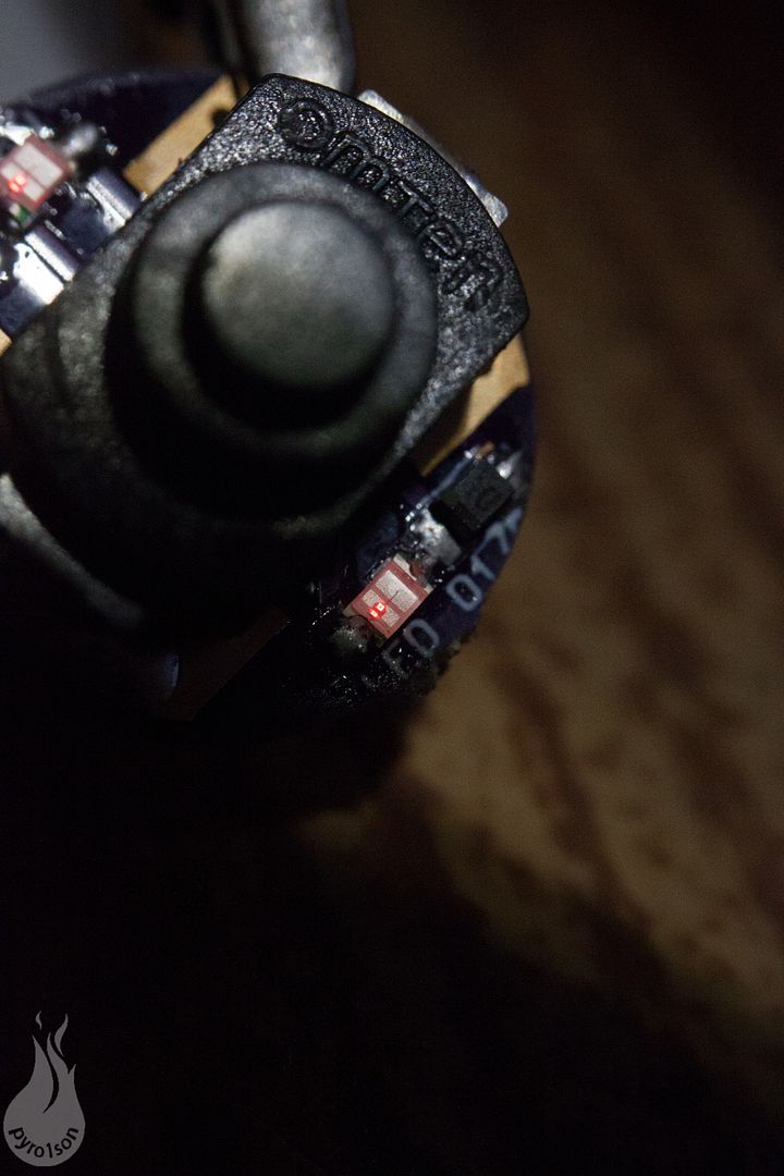
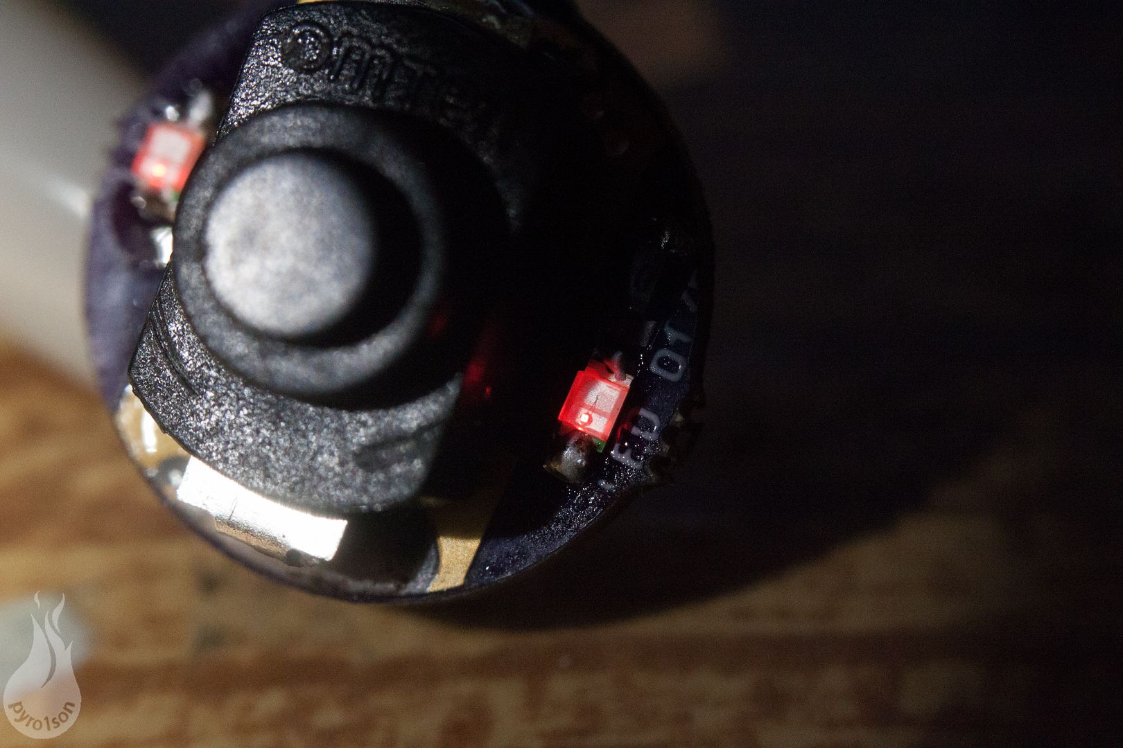
What needs to happen to the driver is that it must be slightly conductive from batt+ to batt-, even when the MCU and led are not powered. Some drivers show that stock, but most drivers need an extra component, a resistor from batt+ to batt-. The resistor value must be low enough to allow enough current for the tail led to light up, and high enough to not cause more than negligable parasitic current drain when the flaslight is switched on. A functional value is 560 Ohm, which causes just 7 mA current loss when the light is on. In my mods I position this 'bleeder' resistor on the battery side of the driver, between batt+ pad and ground ring, but it is probably nicer to find a spot on the component side.
Thank you djozz for the offer.
I need to modify the drivers and tailcaps first to make this work, so it may take a while when I would need one.
Actually, I might buy a new soldering station together with a hot air rework station. Then I could make them myself.
Well over a month after I posted that, I have finally done a full test and it works great. I’m going to stretch it out to 19 or 20mm and update the OP with a lot of the new info we have, “soon”. ![]()
I still haven’t bought any pots, so I used resistors over the pot pads. I tested with a 4.7k and the other empty, and then another test with a 1k on the other pads. As you can see in the video below, it’s very easy to switch between on and off, or between 2 preset levels set with either resistors or potentiometers. (sorry for the portrait orientation of the video :Sp )
Edit: Here is the 20mm stretch of my Rev4 board, now all that’s left to do is update the OP.


Ok guys I’ve updated the OP. I set out to simplify it, but it actually got longer. Hopefully the information is at least more clear and complete. I took the liberty of adding some pictures from others in this thread, if you want me to take your pic down then PM me.
If there are any other sources for anything you think I should add, let me know.
How about the switch itself.
I usually use the switch that came in the light originally, but I’ll see if I can find some Omten 1288’s to add to the OP.
edit: added some links to switches to the OP. Also found some 14mm clear boot covers on KD
Cnqg appears out of stock but last I checked RMM has them loose and Fastech has them mounted.
Ive got everything and built the pcb, but I've either burnt out the leds or they are backwards? I'm not really sure how to know which way they need oriented. I see a green dot on one side, I assumed was the + side?
Look on the bottom, there should be a sideways ‘T’ and the wider/flat side is the + side. If you bought from lighthouse led’s, I believe the green dot is the - side. If you go to the product listing on lighthouseleds it has a picture showing polarity. I always have to check their website when I build a new one.