How quickly does the body of the light get warm or hot?
Well, you mean it supposed to get hot? Haven't felt a tingling of warmth yet, but haven't run it much. After 30 secs, nothing... I'll do a longer test to see.
Do you think it would blow the emitter if left on high? No - believe if the LED is seeing 5.35A, it should live fine, not sure 100% - djozz's tests/threads may say, but I believe over 5.5A is the danger zone for the new XM-L2's (U3, U4).
If the flashlight body gets warm as fast as similar size lights then maybe the heat path from the "pill" to the body is fine. Well, don't have any lights this size to compare with. This is a big light in terms of dimensions and weight. My max modded Shockers that did 6A would get hot in the critical area of the pill, but that's a smaller light and had a lot more amps and heat.
Just did a bit of math
First some assumptions, body shelf inner diameter = 70mm, 5mm overlap so emitter shelf = 80mm
80mm circle = 5026 square mm, 70mm = 3848mm, contact area is 5026 - 3848 = 1178 square mm
A 38.74mm dia circle is 1178.2square mm.
What that means is the heat path is the same as a 38mm dia light, and I have an xm-l2 t6 at 6A using less transfer area than that :bigsmile:
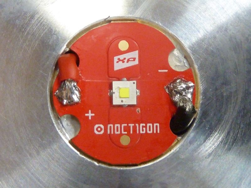
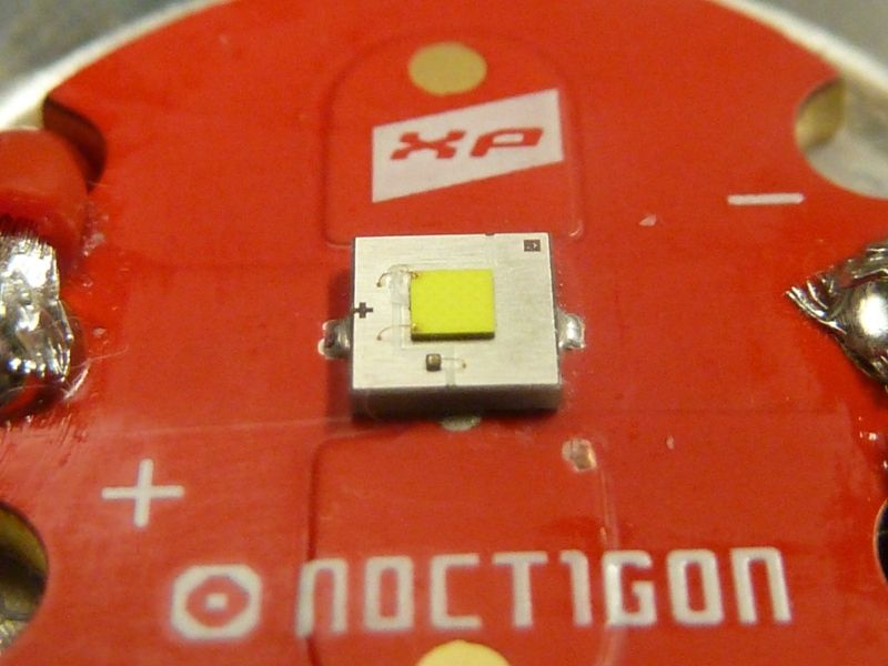
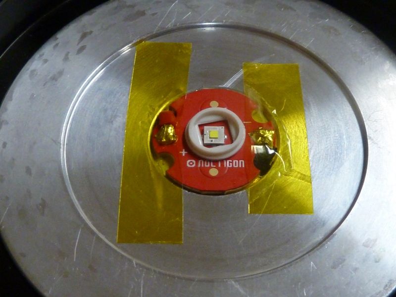
This is a XP-G2 S2 2B de-domed, from an old batch at FastTech. Counting on the twisting of the XP-G2 to self-center in the XML size centering piece. Beam pattern didn't look too bad. As shown above, the centering piece was sanded on the top from 2.09 mm down to 1.76 mm. Didn't fiddle with any focusing, the hot spot looks pretty good, but there is some surrounding artifacts, but it looked well centered.
I didn't expect much with the 4.2A reading - not sure why it's so low. Was expecting over 5A. The tint looks good, the dedome seemed to go perfect, just a little silicone left around one bond wire. I got a dedomed V6 1A to try - might give it a shot.
Still need more time, but here's some notes on it so far:
Well it's one-of-a-kind. Not sure, maybe the largest stock light reflector? Certainly under $100 there is no comparison I would think. There's a bunch or pros/cons. It's certainly moddable, which is great.
If I can't get high performance from an XP-G2, it will be a downer, but if I can get a nice wide beam (well not really wide) from a dedomed XM-L2 or XP-L, I'd be happy, and should hit 600-700 kcd without crazy focusing. I was hoping for like 800 kcd, and still think it's possible, and that someone can achieve it, if this group buy can/will happen.
If the group buy happens for $50 or so, it's a steal to get this kind of size/power. Mechanically, I'm maybe most concerned about the driver retaining ring - I think it can fall apart being so thin, frail. I think the shelf is not such a downer. The wire clearances are always a challenge with this type of reflector design (way too wide bottom). I don't think the driver is that bad as well - it doesn't seem to have bad loss's with mods, least what I seen with the XM-L2 -- it basically hit the max of 5.35A.
I'm thinking/hoping the 4.2A on the XP-G2 is not all the light - something goin on with the LED, but can't be sure at this point.
You could argue for the excessive size/weight, but it's a big reflector budget light with 4 26650 cells -- so what do you expect?
I am hoping that we can get a real good group buy price on these. I think this is a good candidate for those old monster lanterns. A DD driver with a couple modes would make this thing spot on. High for searching and low for "just need a light". Maybe even L-M-H. Best of all...run time.
I have a couple old Milwaukee 28V battery packs that look like they have the paper 26700's. I think they would be perfect for this thing. It is big and heavy but when you need super long run times why not....at least one ;)
I could be up to 10% low on my throw #'s because of 5m measured (happened with a modded TN31), and of course an AR lens difference on top of that could be another 10%, then you are in 1 mile territory. I might do little more testing to see if I can boost the 4.20A, then either dedome the U41C or try a dedomed V6 1A. I really need to test dedomed XP-G2's - maybe this one, try in another DD light, or work on my XP-G2 hot dedoming - I got a ton of obsolete ones for sure, but this time measure before/after Vf at set amps. I think my bench PS is good for that, not sure how accurate, but relative measurements should be fine.
The hot spot sure looks intense...
Post #108. CWK did a pretty good job reporting the dims early on - don't think I confirmed them all, but some dims I took are only fractions off from mine, so I trust his numbers.
I knew I saw it somewhere, but couldn’t find it when I wanted it; thanks. Those dimensions I listed are for the Lum 5-90 reflector. I have one, but haven’t found a light that fits it yet. Maybe with a little trimming…
What kind of kcd do you think we could get from an XHP-50 at max output in a 90mm reflector?
4.35v cells are not as low resistance as the better high performance 4.20v cells. The EFEST 4200 mAh 40A/60A cells I'm using seem like the best cells on the planet right now, least what I'm seeing. I think they are doing little better than 30Q's and HE2's.
Relating to batteries:
The threads on the battery tube are starting to get beat up. It's not easy to start the battery tube threading - you fight the bumps and the threads take the force of it, since they are very pointy (not square) and it's sooo wide, it's really hard to get the threading started now. I'm afraid this is only gonna get worse. I'll have to take a closer look at the thread damage later.
The lack of squared off threads on such a big light might with such resistance of 4 cells could be the worse design issue.
Is there a possibility of contacting the manufacturer to improve the threads on the tube/retaining ring, and maybe the machining of the shelf? Even if it adds $5-15 cost per light it would be absolutely worth it imo.
It doesn't work that way though - you only see 4.35v with no load. They drop like a rock under high draw. I know this from the past, but more recently re-tested - same results, worse than say an HE2 or 30Q, etc.
Also, it won’t take much more to fry the XP-G2… it can usually go up to 5A but isn’t good for much more than that. With some power-on fluctuations and such, gotta be a bit careful not to be too close to the ceiling on those.
Interesting work there Tom, thanks for taking the time and going to all the effort.
with regards to the contact “bumps”, is there a way to mod the whole driver board into something like this from Courui d01? ? No bumps, just flat PCB cut to this or similar shape
that should relieve most of the pressure on threads and even lower the resistance by increasing contact area
Possible I suppose. I looked closer at the thread - don't think there's damage but the anodizing seems to be coming off on the first thread - think that's why it looked worse than it is. Still, it's a challenge every time to get the threading started.
Decided I'm gonna go ahead and piggyback in a 20 mm driver, and go with the U4 1C I was using, but de-domed. I added a couple more trace jumpers, and added 2 screws to secure down the LED shelf. Since the darn thing is so loose, it's a PIA to assemble the light. I'll just add thin layer of thermal grease on the overlap shelf, then the 2 screws will hold it tight all together.
Ohh - the flat edge in the body that the LED shelf rests on is exactly 5.0 mm wide .
 Haven't felt a tingling of warmth yet, but haven't run it much. After 30 secs, nothing... I'll do a longer test to see.