Ok, just got back from Home Depot. I grabbed a 7/8” hole saw bit and a sheet of the cheapest and thinnest plastic sheet. It is sold as a replacement for glass in picture frames. On the left is the ring I made from that sheet, on the right is the nylon ring I had been using. In the middle is what I think I will be using from now on. As you can see the middle one is a lot more translucent than the nylon washer, but should give a more even spread of light than the totally clear sheet from HD. It’s also stronger and less brittle than the clear sheet. Anybody want to guess what plastic I made it from?
Lol brilliant! I ordered 10 and 20k pots, wasn't sure which one would be better.
The sinner modes went finnicky on me yesterday. It wouldnt change groups then it was fine. 20 minutes later it quit changing modes and started comming on on high, 3 minutes later it was back to normal. I don't know why it's doing that, hasn't happened today.
yea I think heat has something to do with it. it would go back to normal after it cooled down. I got the pots and new resistors in, and diodes. I ordered 200mA/30V schottky diodes which seem fine as long as the line is on the right side, which is the left, closer to the LED. With these 120ohm resistors and the new brighter leds I cannot get the modes to work 100%. There is only one spot on the 100k pot that modes will work at all, between 75&80%(3/4 or a little more from full right) and it is always a "next mode memory" even when there isn't supposed to be memory. I am now using a convoy s6 with triple nichia and BLF A6(mtn17DDm) firmware as well as a triple XPL sinner with guppydrv rev1(mtn17DD) for testing, both with 120ohm bleeder resistors.
The 10k pots are small, I haven't tried to fit one yet, kind of doubt they will work. The 20k pots were the right size but they have a tab right between the two legs that wants to contact one side or the other which causes the pot (and leds) not to work at all. More searching through digikey is required for a 20k pot that might work easier, for now I'm just using the 100k.
I paralleled 120ohm resistors and I have the same issue, with modes working fine until the light warms up, and then the modes do weird things, stuck on low, no memory, reverting to turbo then strobe and beacon with normal fast presses, until the light cools and it goes back to normal.
I can't help but wonder if swapping for a different value capacitor would remedy the situation, I hate to go with a bleeder resistor that will let too much more power leak off. Richard told me that I could try it, so that will be the next thing I try.
Well the issue is definitely that the capacitor is being inconsistent. Maybe it’s just a damaged cap, or maybe it does need a different value. I’m not sure, I’ve never had issues persist this long.
I've been using 3 different drivers, one just went to a friend with an s2+. Without the bleeder resistors everything is kosher. I am getting parts for more drivers in the next day or two so I'll swap drivers with different value capacitors when I get a chance. These drivers don't look fresh and clean anymore after all the flux I've used so they need cycled out anyway lol
So, I pulled the bleeder resistors off the drivers and I'm still getting a parasitic drain. Has to be a bad component on the drivers. They weren't doing this before so I wonder if something in the lighted tailcaps caused the failure?
How much parasitic drain? The lvp circuit lets some current through, but normally the tail switch stops that when the light is off. Since we essentially bypassed the tail switch with the LTC, it allows the lvp voltage divider to drain some.
I have had issues with the Convoy S2 triple that I built. If I run it on high for very long and then shift modes, I do not always get the mode I want. Sometimes it is back to ML or further back to battery check. I am pretty sure it is a heat issue, if I avoid the top 2 modes things stay good and a couple minute cooldown brings back normal function. Bear in mind, this is a triple on solid copper with a FET+1 running BLF A6, a lighted tailcap battery + contact is a copper disk and tailcap spring is bypassed. I run it with a 30q, so the power is flowing freely! Draws about 5.2 amps at start on high!
It serves duty as my nightstand light and an occasional holy crap light when someone wants to see one.
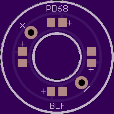
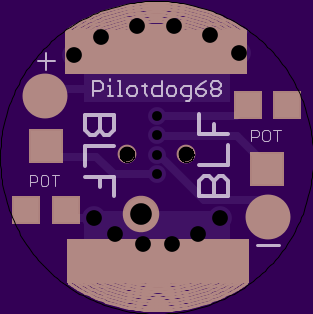
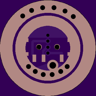
Alright, this version is a little different. This time the led’s (4 of them) will be mounted on a ring that’s designed to replace the clear/translucent washers we have been making. You should still be able to use the older versions as the bottom pcb’s for the switch, but I also made a new main pcb with larger solder points to attach wires to connect the two boards. On my version of the bottom board the pots will be basically inaccessible once you stack the top board, but pyro’s bottom-pot board obviously won’t have that problem.
Can you explain a little more on these? The image on the left is a single board to mount the led’s on, and the images to the right or the opposing sides of the same board, correct?
Very good thinking, this will get the light much more efficient in the boot cover, and solves the availabilty problem of the clear washers.
Can I request (only if you have time and feel like it) a simple version of the board where the switch is mounted:
-only suitable for the small type Omten (because of next requirement)
-solderable vias (instead of pads) for connection to the washer-board adjacent to the switch direct under the vias of the washer-board. The plus-via therefore must end on the spring-side of the board without connection to the batt-minus ring (small insulating ring around it).
-no pots, just pads for one resistor. Thusfar I only used the pot once for setting and left it alone, so a resistor will work just as well for me.
Djozz, I could modify the base board like you said with the isolated via for each of these wires to go through, or if all you want is just one resistor, I could put that resistor up on the top ring with the LEDs, then you could just connect the top ring to the bottom using the big main switch pads. Would that work just as well? That way it could easily be added to any stock switch PCB.