I saw that a few months ago, what a great thread, one of the best I’ve came across at cpf!
Don’t sweat it. I know that if you’d had what I needed you’d have gladly sent it over. It appears that I left quite a bit of wiggle room for that diode in my own layout. I think that I have some much larger diodes on hand here with similar forward voltage drop. It’s not really the same thing but it’s probably enough to get things started if I can’t scrape up any BAT60A for the moment.
As for the link to the wrong thread - let’s face it, we are interested in both topics! I want a high-quality single-lion boost driver for 6V LEDs as well, it’s just as separate project. I’m glad you linked to it.
Thanks Gunga. If it’s PAM2803 (learn to identify w/ #10 here) you may want to hang onto it so that you can build one of these yourself. ![]() Since I’ve already got 3x of the donor driver on order from FT the only thing I’m really looking for ATM is that specific diode mentioned above. Once we can insure that that diode performs as expected and nail down another thing or two the layout may change. (Since that diode is so small it allows for changes.)
Since I’ve already got 3x of the donor driver on order from FT the only thing I’m really looking for ATM is that specific diode mentioned above. Once we can insure that that diode performs as expected and nail down another thing or two the layout may change. (Since that diode is so small it allows for changes.)
This person is awesome. They seem to be what most of us dream of being… designing and building drivers, doing firmware, turning flashlights, knurling, etc… all the while documenting it with pictures. I’ve jumped into the thread a couple of times since it was linked in this one - lots of great work to see.
Thanks, lots of heavy reading but I plowed through some this morning then looked at the images. What I had in mind was not so ambitious but while trying to generate a 2803 eagle part was mulling this over. With the device done I’ve started on a schematic for two boost ic’s. Not on at the same time but connected to 13A pins 5/6 and pam switch pins(simple on5 or on6, no pwm). Should be room for that if all the caps are on the bottom. Might even be able to put the shottky in the middle of the spring pad. As you say, there’s probably not room for the complexity of the dqg driver on a 15mm driver and I’d prefer to to maximize efficiency by avoiding pwm. Is there an inductor device in eagle libraries the correct size or do I need to make that library part too?
wight wrote:
Does anyone in the USA have a few of the schottky diodes to spare? I don’t want to mooch, but I also am not ready to place an order with Mouser/Digikey at the moment. I’d be happy to trade something to cover the parts and postage (mosfet(s), 7135(s), PCB, etc).
Those 3 amp jobbers HQ alerted to? I have some that I picked up off Ali. Haven't used any yet. You're welcome to a handful. Just PM my your address and I will get them in the mail tomorrow.
No problem. I wasn’t really trying to suggest that your idea was as complex as the DQG driver or that it needed to be. Make sure you’ve got space in the light for all of that stuff you want to put on the bottom. I don’t think that all AA lights which use 15mm drivers have space for components/springs/etc on the bottom, right?
I’m right there with you on avoiding PWM, although I don’t know how much it’s going to improve efficiency…
As far as an Eagle Part, what I’ve got on my (untested!) PCB is POWER INDUCTORS SMD CR Series with “CR32” marked for both the Package and the Value. Looks like it’s from the stock “inductors” library. I don’t know that it’s the right one or a good fit for the harvested component; I think that the Eagle part is around a 3.5mm or 4mm inductor. I just put mine on big pours for now so that it can be fixed with scraping. I sure do mention scraping in a lot of my driver threads… ![]()
Thanks ImA4Wheelr, PM sent. I’ll be frying PAM2803’s before we know it. ![]()
Thanks Alex, I saw that part # but the eentsy picture in the library window doesn’t help much. As you say, as long as it’s close then good enough for now. I really have no idea what the best way to proceed is just figured on throwing ricks until something breaks. Hopefully several approaches can lead to one good one.
Wight, really happy to have you back in.
.
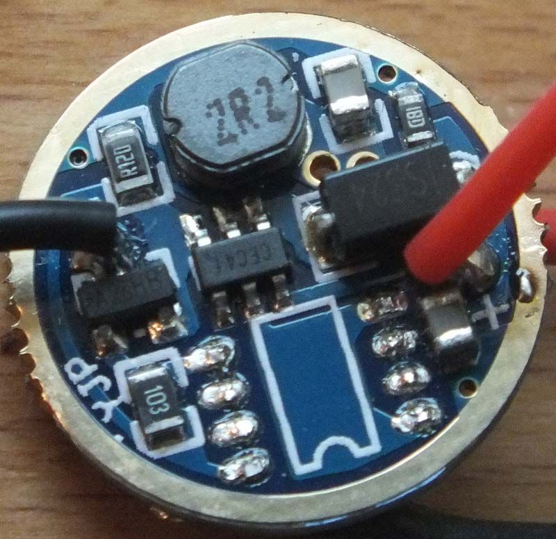
This picture is closest to a ‘stripped’ version of the FT driver I have at hand. It’s the exact driver I did modify, pic taken while in the process of swapping MCUs. What you can’t see is the connection between pin4 and pin6 under the PAM2803.
.
.
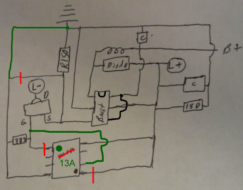
There is the other thread where we discussed the boost driver and @ImA4Wheelr had drawn a schematic of the FT driver. Just borrowing, hope that’s ok.
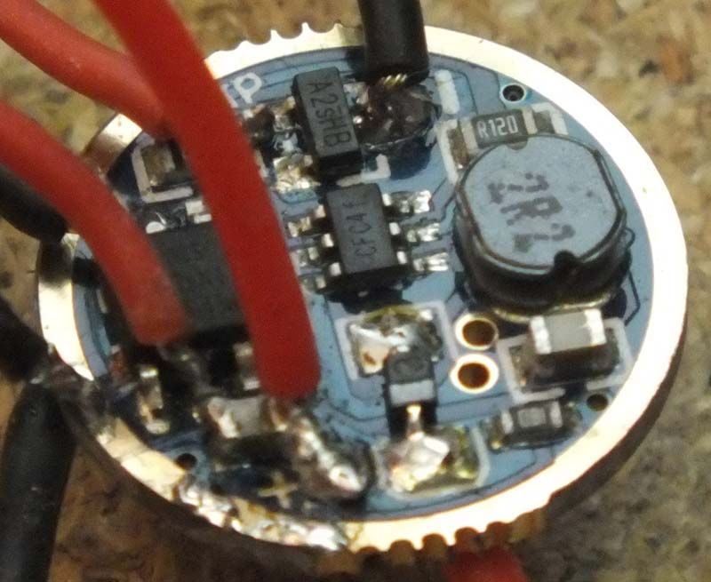
My successful Mod was this:
[EDIT: new picture, first picture was missing the connection between MCUpin6 and FetGate (the PWM signal).
.
.
Thanks for stepping in ![]()
The BAT60A is quite easy to source in Europe but plays hard to get overseas.
I had briefly tested the BAT60A on my modded FT driver as well and it worked.
.
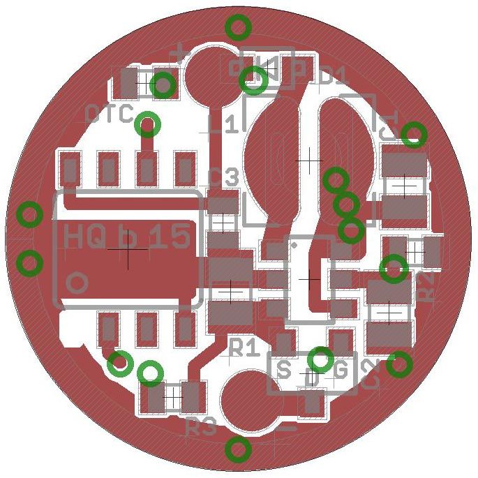
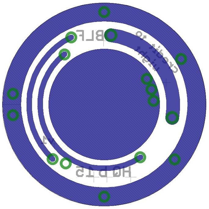
This is the layout I used for the board, presumably following the circuit of the modded FT driver.
Including R2 and R3 (well, it had worked with them…).
C2 and C3 are in parallel, C2 as close to PAMpin5 as possible and C3 as close to MCUpin8 as possible
R and C (0805 or 0603) are almost all reduced in size.
L is 42mm and the part selfmade (part is only tDocu, pads are simple layer 1 current paths). Eagle inductors are scarce.
Overall size is 15.4mm to ensure a GND ring of about 15mm.
Well, FYI:
.
.
HarleyQuin, that’s a pretty clear pic. Looks like they’ve bumped down from R150 to R120 for a small increase in output? Probably just whatever was cheapest at the time but R12 is the right component since FT lists it as an 800mA driver.
HarleyQuin and I recently talked about what the two “extra” resistors are doing in there. I noted that they were not part of the application circuit and HQ pointed out that they are present on the working design sold by FT. The resistors in question are the two 0603 seen in post #57. According to HarleyQuin’s circuit the 33k one connects gate to GND (through Rsense) and the 150k one connects Vout/Vcc to GND directly. The 33k one seems to be a pulldown resistor for the transistor, but the 150k one… no idea really.
The following is probably another case of “whatever is cheapest” but I noticed that on one of the no-MCU versions FT sells there is clearly an R150 for sense and an R150 connecting LED- across where the missing transistor is. It’s hard to see on the other no-MCU listing, but I think that one shows a zero-ohm jumper. Again, I seriously doubt that any of that is relevant.
FWIW what both no-MCU examples do show is that these two resistors are not populated (333/33k and 18D/150k) when the MCU/transistor is not populated! Maybe the 150k is a bleeder to help ensure clean mode changes? This is something that RMM just pointed out in another thread when the topic of using an LDO in a clicky came up. I feel decently confident on that now, that’s probably what we are looking at.
Come to think of it, does HQ’s recent pic showing the FT board with MCU removed show that the MCU ground is on the sense side of Rsense? (eg both the pulldown and MCU GND are not connected directly to GND?) Is there any significance to that?
This might be due to differences in the MCUs (Attiny vs PIC?)
When I first swapped MCUs I connected pin4 of the Attiny13a as it was with the original MCU, not directly to GND but to the other side of Rsense. That did not work. Modes would not change (I briefly wrote it in Post#57). So I furthermore cut the trace to MCUpin4 on the board and connected MCUpin4 to GND and the driver worked.
Thanks HQ, that gives me a bit more confidence to proceed. I doubt I’ll be as creative as you but it will at the very least waste a few days.
Ah, thanks HQ. I feel really off balance after my time off from the forum. ![]() You did specifically talk about that in post #57, I just didn’t absorb it when I looked at your post. I’m not 100% sure what’s up with the weird GND path for the existing MCU on the FT driver. IIRC we may have seen something similar in ImA4Wheelr’s HX-1175b1 thread? I dunno and I’m not going to try and hunt it down right now. I do strongly suspect that I’ve seen similar wiring on another Chinese driver. For me it’s good enough that you noticed the same thing, tried it with the ATtiny, and ended up changing it to a direct GND.
You did specifically talk about that in post #57, I just didn’t absorb it when I looked at your post. I’m not 100% sure what’s up with the weird GND path for the existing MCU on the FT driver. IIRC we may have seen something similar in ImA4Wheelr’s HX-1175b1 thread? I dunno and I’m not going to try and hunt it down right now. I do strongly suspect that I’ve seen similar wiring on another Chinese driver. For me it’s good enough that you noticed the same thing, tried it with the ATtiny, and ended up changing it to a direct GND.
On a side note HQ, do you really work with your Eagle set to a white background or do you just do that for screenshots? I just tried it and ouch it didn’t feel good - especially with both the bottom and top stuff enabled at the same time, where I spend a fair amount of time. Maybe I’d get used to it. ![]()
![]() For anyone who doesn’t use Eagle: the default is black like in the screenshots I sometimes post.
For anyone who doesn’t use Eagle: the default is black like in the screenshots I sometimes post.
I don’t yet understand how the lack of the pulldown/bleed resistors would burn a PAM2803. Hopefully when the parts to build this thing show up I’ll be really motivated and setup the scope. (I laid out a lot of cash for that thing, we should get some use out of it…) With the scope on 1xAA we can observe the behavior without the pulldown/bleeder. Then install them (stack the bleeder on the output cap and airwire the pulldown) and check everything with the scope again. With any luck this will demonstrate any spikes they may help minimize without burning the PAM2803.
I don’t have much to contribute here, other than to say I also use a white background and it definitely was the default when I installed Eagle.
In the board editor? Crazy! Since my memory is on the foggy side I had to do a sanity check - sure enough, in the past black was the default. A quick Google Images search for eagle+board+editor corroborates this. I wonder why they changed it?
I should point out that all I posted are more or less singular events. It was one PAM2803 that released smoke, one successful rebuilt FastTech driver, one built HQb15v1 that did not work as expected (3 modes, mode change works, but flickering in all modes). I can’t explain what happened or went wrong. It’s not that I was setting up test series here…
.
The PAM2803 that died was on a Nanjg110. I had only 2 more at hand at the time and did not want to lose them. Then the FT board arrived and I went with them - including the reistors.
.
The resistors (that I dubbed R2 and R3) are, as @wight pointed out, only present on the boards with MCU. They were not needed when I tested the BAT60A on a single mode Nanjg110 (post#35). But I don’t know what these resistors are there for on the FastTech driver.
R2 (“18D” = 150kOhm) is between LED+ and GND.
R3 (“103” = 10kOhm) is between FetSource/PAMpin3/Rsense and FetGate/PWMsignal.
.
The HQb15v1 I did model after the successful FT conversion. Can’t say whether I misdesigned it, a part is defect or I did a bad (rework-station-) solder job. Next weekend might show, hopefully.
.
I started using Eagle in summer ’14, installed it on 2 PCs and have never seen anything but a white background. Needless to say, I’m simply used to it.
.
I’m aiming for 1AA and 2AA operation, 2AA for several Mini Maglites which can so nicely be converted to a triple using a modded P60 pill. Very family friendly for those I don’t want to burden with lithium-ion cells.
In the past editions it was black and I always switched to white so I could see where the cursor was. Images seem more striking on a black background so I switch to that for screen shots.
Heh, maybe the “more striking” bit is a concentration aid for me. ![]() I use the default cursor which is “inverted” from whatever it’s hovering over (black = white, red = blue, green = pink, etc). Since I was curios I checked it out on both backgrounds just now. I actually find the cursor easier to see on the black background. Did you check out the “Large” cursor while you were in there?
I use the default cursor which is “inverted” from whatever it’s hovering over (black = white, red = blue, green = pink, etc). Since I was curios I checked it out on both backgrounds just now. I actually find the cursor easier to see on the black background. Did you check out the “Large” cursor while you were in there?
No, just the background color. I’ll have a look next time I’m in there.
Liftoff, we have a liftoff…
15mm boost driver (v1) working
.
Partlist and used Firmware below
Rebuilt on a 2nd board, running fine.
2x 2AA and 3x 1AA (Eneloops) drained so far, about 200 mode changes, all good.
It’s a HQb15 de-luxe with Coilcraft inductor and high value capacitors.
Board is the same layout as in post#72 above.
.
Oshpark link for HQb15 v1 EDIT: Obsolete as HQB15 v2 is finished, see post#96


.
Driver height with this inductor is 3.7mm (0.2mm less than with the FT inductor). Now take the new Oshpark 0.8mm boards and you’re down to 2.9mm. That’s a whopping 3.0mm less than a Nanjg110.
Enough space around the Attiny13a for the clip after driver assembly.
.

.
Partlist
(source in brackets; see post#25 for more info on the parts)
Switch: PAM2803, SOT-23-6 (FastTech driver)
L1: 2.2yH, Coilcraft XFL4020 (electr. supply)
D1: BAT60A (electr. supply)
C1: 10yF, 0805, X5R (electr. supply)
C2: 20yF, 0805, X5R (electr. supply)
C3: 4.7yF, 0603, X5R (electr. supply)
R1: 0.120Ohm, 0805 (FastTech driver)
R2: 150kOhm, 0605 (FastTech driver)
R3: 33kOhm, 0605 (FastTech driver)
MCU: ATTiny13A-SSU, Package 8S1 (electr. supply)
OTC: not yet
FET: (FastTech driver)
C2 and C3 are by design in parallel (C2 for PAM2803, C3 for ATtiny13A). In this built I used both caps and with high value.
.
Firmware
An adapted Dr. Jones MiniDrv firmware for starters.
Frequency changed to 18kHz, on-time-memory, 9 modes
.

.
Output
Eneloops fresh from charger (no resting time)
With 2AA holding ~780mA for quite some time (R1 (=Rs) = 120mOhm)
With 1AA starting >550mA, continuously going down, but surprisingly slow in comparison to Nanjg 110
.
loose threads…
no OTC yet
adapting R1 to change output
output at PWM1 is 16mA with fresh cells (1AA and 2AA)
trying different components (inductor, FET)
17mm version
15mm V2, will be a fine tuning of the layout after having built them twice
V1 has an overall size of 15.4mm, the GND copper layer by Oshpark is only 14.8mm. V2 will be increased to 15.6mm.
(EDIT needed after Drupal overhaul)
Wow! Wow! Can’t wait to see the progress!