Hi Alex, just looking to get a baseline since hopefully there will be others to compare it with at some point.
Thanks for the encouraging comments.
True.
Knowing there is test-personnel standing by ![]()
It’s only that wife and kids are now wondering why I’m so absent minded again, not paying attention, mumbling strange words like sense resistor and redundant components.
.
I can’t provide data as HKJ does in his tests. Best I can do is I-in vs I-out. Even this has already proven to give different results depending on the eneloop used (hot from i4 charger or resting from Opus-charger). My testing procedure isn’t remotely accurate enough to invest time here.
.
The working second HQb15 v1 has no parts of the first one. I laid the 1st one aside after already checking continuity and having resoldered where I could with the iron - to no effect.
The 2nd one was a complete fresh start. New board, new FT driver, new components. Testing continuity on the complete board, testing the FT driver before desoldering (hadnt done that with 1st one) and taking unused additional parts.
My best guess for the 1st one: Bad solder connection / not enough solder paste somewhere. Perhaps a faulty component as a distant second.
For now I’ll leave R2 and R3 in the design, but I’m couriously expecting your test results.
.
Could you kindly explain the reason behind this. Unless I’m mistaken (and I could very well be) in this boost circuit the FET does not draw current directly from GND. It’s coming via Pin3 and Pin2 of the PAM2803. I might thicken this path, though.
V2 inbound, thatfor I’ll skip V1 link.
@HQ - sorry if this seems obvious or I’m missing something but if the negative connection to the battery tube is on the spring side then current from L- goes through the pwm controlled fet from drain to source and then through the board. Other components are grounded as well but the vast majority of the ground side current follows this path and just as the positive side needs short, generous traces/vias along the Vin - Led+ path, so does this. There are other gnd vias sure but straight through from the fet is the shortest path. Not a big deal at low current but still something I would normally suggest.
This is where I have more interest.
But it’s great to see the drivers built by this community growing!
@RBD
Thx for explaining your thoughts. The through the board part was indeed obvious to me. It was the at the FET part, which I translated to: bottom right of the driver, that made me wonder. I think the current goes from L- to FET to PAMpin3-pin2 to the left center of the board, so vias at the FET sounded odd.
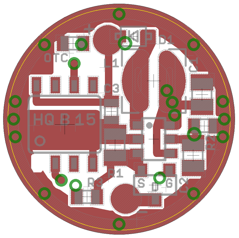
Anyway, I added vias. Doubled them, actually. Even made them symmetric…
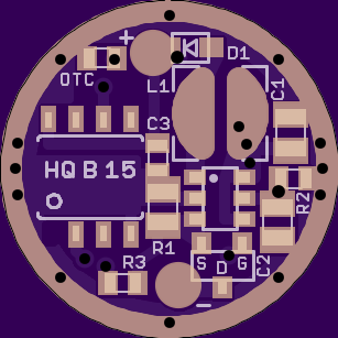
So here is HQB15 v2.
This board is provided as is, and yet untested
Partlist and Firmware see post#84
.
.
Changes from v1 to v2:
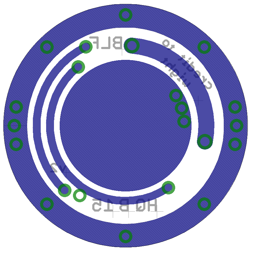
Size increased to 15.6mm, the copper GND ring should now result in full 15.0mm
PAM2803 now has a Pin1 dot that appears on the board
Several component positions slightly adapted
A lot of paths widened
GND vias doubled and rearranged
.
The yellow circle is not in the actual board, it just indicates 15.0mm
.
Will this driver survive a liion like most other boost drivers nowadays, or will it release the magic smoke?
@gisewhcs - It’ll probably survive, but for now that is certainly not important to me. I can’t speak for the others who are working on this. As far as I know, this normally results in unregulated PWM-adjusted output levels which aren’t as bright as DD. I should already have a 15mm DD+1 driver somewhere, check the list in my signature. This driver also does not have a voltage divider. It cannot measure battery voltage and has no LVC / LVP.
If we achieved programmable regulated no-PWM output on a double sided or 17mm board (by biasing the feedback pin) I think that a li-ion cell becomes more of a problem. In that case the li-ion would probably eliminate modes in addition to it’s other drawbacks. I haven’t fully considered this statement, so it may not be true.
I just had an idea. I know this idea I just had is nothing like the intended purpose of this driver, but I don’t know a better place to ask about it. What would be the feasibility of building just the boost circuit into a tailcap pcb? I was looking at PD’s lit tailcap thread, and lots of things are going on there, but this idea wouldn’t fit there at all. If the boost driver could be fitted to a tailcap pcb, then the actual control driver in the head could provide all the modes and such that we’re accustomed to having in our lights. The tailcap would be the only part that would have to be modded, and the “danger” of li-ion going “direct drive” through the boost circuit would be moot, since the drivers we use take “direct” power from li-ion on their inputs anyway. Can this be done? Is it worth doing? I just thought being able to simply add boost capability to any light at the tailcap would be a neat thing to do.
That puts the LED on the low voltage/high current side of the boost circuit. Not sure what the point would be.
I don’t know what you mean. I figured the boost circuit would be used to boost the power on the negative side, after the switch, before the connection to the battery tube that would run up to the ground ring of the regular driver. I know it isn’t the direction boost drivers are normally made to work, but I thought it might have a chance if specially designed that way by someone in this forum.
Thinking on it some more, maybe I should have started a new thread. It might get better visibility from more people. And, I don’t want to be guilty of hijacking wight’s thread, here.
Boost circuits have input and output sides with different current and voltage on each side. Having it in the tail automatically places the LED on the input/low voltage side. without running extra wires to the front I’ve no idea how this could be changed. It’s not like the illuminated tail cap which uses leakage current only available when the light is switched off. A possibility for lights with multicell carriers but not inline tubes.
RBD is entirely correct. Without trying to be mean (but probably succeeding anyway…) your suggestion makes no sense in either the way you intended it or in the context of the way this stuff actually works.
As I take it your intention was to boost the voltage to the entire light by way of a circuit in the tailcap. Of course the boost circuit would create all of it’s normal losses in that position just like it would in the “normal” position (say 70% efficient maybe). Your suggestion entailed a normal driver in the normal position… so I’ll take that to mean linear driver. So there’s another source of losses (say 70% efficient if you have a low LED Vf and a high boost voltage). Now that we’re on the subject of voltage, how would we regulate the boost circuit in that scenario? Voltage or current?
Of course that remains a moot point since, as RBD mentioned, it simply doesn’t work that way. Simply put, we cannot put a boost circuit in the tailcap for the same reason we cannot put any other power supply circuit in the tailcap. If that could be done we’d have a much, much larger interest in momentary lights since all of our tail-clicky lights could be converted to momentary by moving the driver to the back.
Additionally , the DD part isn’t what’s dangerous with the li-ion. The problem is that this driver does not feature any LVP AND it is a boost circuit… so I suspect that a person could easily damage a li-ion cell. (The circuit should start smoothly boosting as the voltage falls enough to cause the LED to get unreasonably dim) If we had space for multiple circuit boards in the light (as you suggested) we’d have enough space for the two resistors required to do voltage monitoring and have LVP. We do not have that space in all AA lights, which is why this driver doesn’t have a voltage divider / LVP. The boards we are discussing currently are single-sided. A double-sided board would have enough space to add a voltage divider easily, but would add at about 2mm to the overall thickness. We can certainly visit that issue after the boards are cranking along nicely on AA’s. To be 100% clear: AFAIK no LVP is the normal configuration used in AA/AAA lights from DQG to KD Buckle to SK68’s.
… Finally, and I’m sure I’ve mentioned this before… and it’s just an opinion I suppose… but personally I don’t see the utility in a light which can take both. Clearly the intention is that if I leave the house in the morning with a 14500 in my light and then I run down the 14500 I can go to the store and purchase a regular AA… but that’s just nonsensical to the extreme in my opinion. Why not simply keep a backup light which takes regular AA’s in my glove box? That would save me a trip to the store. It seems safe to assume I just don’t have time in my day to go buy flashlight batteries on a day where I’m apparently so busy that I run my flashlight batteries down! You’ll get better performance with a DD driver on your 14500 light. The backup light in the glove box can be a much more efficient 2xAA model or a 2xCR123A model or whatever is appropriate.
I just want AA compatibility. I don’t care about 14500 myself.
Never fear Gunga; AA compatibility will certainly show up before anything else! ![]()
I’m very encouraged by HarleyQuin’s results and I look forward to playing around. My hands are tied until donor drivers show up with PAM2803’s. Tracking isn’t showing much, hopefully they’ll show up any day now.
Just finished an order for 3 Nanjg 110’s from RMM. Also now have a couple of the dirt cheap Xpe boost lights someone was borrowing from. Now all I need is time. I’ll try and find the time to open one up and have a look at the driver.
Can the shottky diode be stacked or paralleled to gain performance in a smaller package?
Ideally we don’t stack/parallel diodes, but yes it’s possible. They must be “thermally coupled” to avoid death. In practice it seems that installing them side by side is a good enough thermal couple for us. With that said, I’m not sure why we’d need to with the BAT60A diodes mentioned in post #35.
Some cheap sourcing.
A member earlier posted a thread on This AA/14500 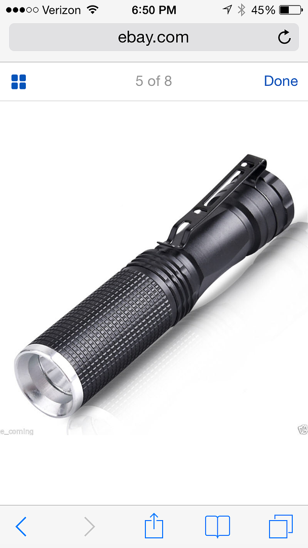 light from eBay which was $2.58 each when I bought 2 last month and contained this driver.
Removable threaded pill so easy to mod and you get what looks like a nanjg 110 and host for not much more than the driver alone. Bought it mainly for swapping into Incan minimags after reducing current for 2xAA to around 150-200mA. Switch doesn’t look worth much but lens and reflector ok to use.
Thanks for the explanation, wight. I think I understand now. And your post didn’t seem mean at all to me.
Thanks to RBD as well. You were trying to tell me. I just couldn’t get it, because I don’t know how driver circuits work.