I have had issues with the Convoy S2 triple that I built. If I run it on high for very long and then shift modes, I do not always get the mode I want. Sometimes it is back to ML or further back to battery check. I am pretty sure it is a heat issue, if I avoid the top 2 modes things stay good and a couple minute cooldown brings back normal function. Bear in mind, this is a triple on solid copper with a FET+1 running BLF A6, a lighted tailcap battery + contact is a copper disk and tailcap spring is bypassed. I run it with a 30q, so the power is flowing freely! Draws about 5.2 amps at start on high!
It serves duty as my nightstand light and an occasional holy crap light when someone wants to see one.
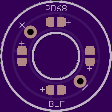
Alright, this version is a little different. This time the led’s (4 of them) will be mounted on a ring that’s designed to replace the clear/translucent washers we have been making. You should still be able to use the older versions as the bottom pcb’s for the switch, but I also made a new main pcb with larger solder points to attach wires to connect the two boards. On my version of the bottom board the pots will be basically inaccessible once you stack the top board, but pyro’s bottom-pot board obviously won’t have that problem.
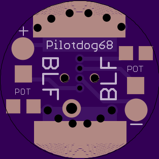
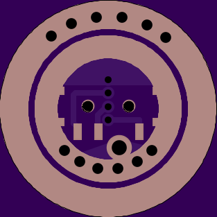
Can you explain a little more on these? The image on the left is a single board to mount the led’s on, and the images to the right or the opposing sides of the same board, correct?
Very good thinking, this will get the light much more efficient in the boot cover, and solves the availabilty problem of the clear washers.
Can I request (only if you have time and feel like it) a simple version of the board where the switch is mounted:
-only suitable for the small type Omten (because of next requirement)
-solderable vias (instead of pads) for connection to the washer-board adjacent to the switch direct under the vias of the washer-board. The plus-via therefore must end on the spring-side of the board without connection to the batt-minus ring (small insulating ring around it).
-no pots, just pads for one resistor. Thusfar I only used the pot once for setting and left it alone, so a resistor will work just as well for me.
Djozz, I could modify the base board like you said with the isolated via for each of these wires to go through, or if all you want is just one resistor, I could put that resistor up on the top ring with the LEDs, then you could just connect the top ring to the bottom using the big main switch pads. Would that work just as well? That way it could easily be added to any stock switch PCB.
I’m afraid to order some boards, because the next day PD will have a newer, even better version up.
I thought a bit about the MCU-controlled tailcap, the circuit shouldn’t be that difficult. Kinda like a 105C reversed without the AMC’s. Don’t know if caps or diode are necessary, though. LEDs could be driven directly by the MCU, right? Don’t know if that fits on one single board. MAybe a smaller footprint MCU to go under the spring or so and some traces and vias to programm it in system. Man, I have to get into this Eagle stuff…
I think with this stacked board we just might be able to fit an attiny up there. The rest of the circuit would be easy, but I would have no idea how to code it.
You can definitely get them down low. I helped Dale with resistor values to adjust his special editions. He got them down to 0.14ma draw. I recommend the 50k pots. On my board you can use just one pot, but it’s a little useless without the mini slide switches.