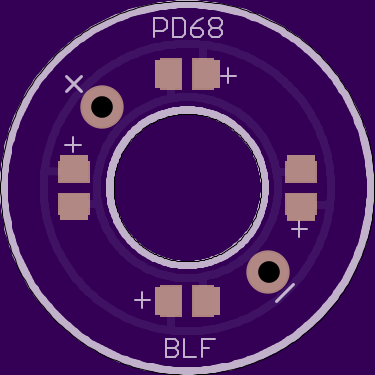
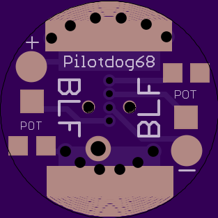
Can you explain a little more on these? The image on the left is a single board to mount the led’s on, and the images to the right or the opposing sides of the same board, correct?
Yes, That’s correct
I’ve put the pictures on seperate lines now.
I believe you are correct left board goes on top of switch in place of washer.
How and where did you measure? Does Nanjg105c need a bleeder? Thanks!
Very good thinking, this will get the light much more efficient in the boot cover, and solves the availabilty problem of the clear washers.
Can I request (only if you have time and feel like it) a simple version of the board where the switch is mounted:
-only suitable for the small type Omten (because of next requirement)
-solderable vias (instead of pads) for connection to the washer-board adjacent to the switch direct under the vias of the washer-board. The plus-via therefore must end on the spring-side of the board without connection to the batt-minus ring (small insulating ring around it).
-no pots, just pads for one resistor. Thusfar I only used the pot once for setting and left it alone, so a resistor will work just as well for me.
Djozz, I could modify the base board like you said with the isolated via for each of these wires to go through, or if all you want is just one resistor, I could put that resistor up on the top ring with the LEDs, then you could just connect the top ring to the bottom using the big main switch pads. Would that work just as well? That way it could easily be added to any stock switch PCB.
even better, very versatile! 
(with the resistor on the top board you could even designate a separate resistor to each led individually)
no, scrap that, overkill 
I do like 6 leds instead of four though...
(this is a clear sign of decadence, I admit)
edit: scrap that too, if you wish
I have an idea… But it will have to wait for tonight
I thought about six, but I figured it would make it hard to just use two on that layout. You’d have to use at least three
curious...
I think you’ll like what I have in mind, I just need to figure out the easiest way to do it
there's (ok, relatively) loads of space on the back of the top board to do some fun stuff: a KIT-light with a round-running led
I’ve got a plan and it involves thirteen 0805 sized pads
Oh my..
PD is on fire!
I’m afraid to order some boards, because the next day PD will have a newer, even better version up. ![]()
I thought a bit about the MCU-controlled tailcap, the circuit shouldn’t be that difficult. Kinda like a 105C reversed without the AMC’s. Don’t know if caps or diode are necessary, though. LEDs could be driven directly by the MCU, right? Don’t know if that fits on one single board. MAybe a smaller footprint MCU to go under the spring or so and some traces and vias to programm it in system. Man, I have to get into this Eagle stuff…
Dude, you are on fire! Does one need to use 2 pots or just one? Are these way to bright for the bedside now, or can they be adjusted down very low?
I know, here I go again with questions…
Matt
I think with this stacked board we just might be able to fit an attiny up there. The rest of the circuit would be easy, but I would have no idea how to code it.
You can definitely get them down low. I helped Dale with resistor values to adjust his special editions. He got them down to 0.14ma draw. I recommend the 50k pots. On my board you can use just one pot, but it’s a little useless without the mini slide switches.
NICE!
But I admit, I’ve no clue how to code it, too. Something like Battcheck maybe…
As for the stacked board, you think the LEDs would go right under the boot? It’s the thing that presses the tailcap boot against the housing to make a sealing, right?
yes, this ring replaces the washer, putting pressure on the bottom of the boot to seal it up. I measured the tailcap area to make sure there were clearances for everything set up for 16mm boot. On that note, I might recommend ordering these in the normal OSH thickness, instead of the thinner type they just announced.
I’ll try to draw up a board with an attiny tonight, then we can have some leverage to convince the firmware people to write something for us ![]()